Authors: Jack McLean, Tim Bettelley.
ABSTRACT
Where corrosion activity can occur on the internal surfaces of steel structures (vessels & pipes), Cathodic Protection (CP) is often used as a viable prevention solution. In many instances however, these systems have been designed and installed without consideration for future upgrades, repairs or maintenance. This often means that system componentry, such as anodes and reference electrodes, are permanently fixed to the inside faces of these structures in such a way that accessing them in future is unfeasible from both a practicality and occupational safety perspective, often necessitating plant shutdowns, drain down of areas to allow access with associated disruption to normal operations.
In order to address these issues, a retrofitted solution must be developed and implemented that will not only address the current protection requirements of the asset but will also take into consideration how future repairs and maintenance will be undertaken including ready replacement of componentry without incurring major disruptions.
This paper focuses on the challenges faced for asset owners and corrosion control practitioners when existing, inaccessible, cathodic protection systems for internal surfaces have reached the end of their design life. This will be discussed within the context of a cathodic protection system upgrade of a sewer outfall pipe network in Sydney, NSW and how a proactive, risk-based decision-making process was undertaken to address the potential risk of future corrosion activity, whilst ensuring CP equipment could be removed and replaced without the need for plant outages or downtime.
Keywords: Steel, Cathodic Protection, ICCP
Introduction
The risk of internal corrosion activity for steel vessels and pipes can present significant challenges for asset owners. If not managed proactively, this form of corrosion can be aggressive, rapid and difficult to identify until failures and leaks occur.
This paper discusses the challenges faced when corrosion mitigation strategies (such as cathodic protection) for enclosed pipes and vessels have reached the end of their design life and are not easily accessible for repairs or maintenance. The paper explores one such example of a recent project undertaken at the Bondi Water Resource Recovery Facility (WRRF) where an ageing cathodic protection system installed on the inside of a pipe network was no longer accessible, however required renewal and replacement.
As part of this paper, a review of the following items will be undertaken:
- A review of the corrosion mechanism for internal steel surfaces
- An exploration of the commonly used mitigation solutions, and their benefits and drawbacks
- A discussion of the Bondi WRRF case study project, including:
- The history of the plant, pipe network and cathodic protection system and identification of the
- The optioneering and workshopping process – An exercise in risk management for asset owners
- The design and development process – A novel installation concept
- The installation & commissioning of the chosen
Corrosion of Internal Surfaces
Corrosion of internal surfaces is a very common occurrence in pipes and vessels used for the transportation and storage of water and wastewater products. Resulting from the electrochemical reaction of the steel material with the electrolyte (water) in the vessel, internal corrosion commonly results in either general wastage (uniform corrosion) or highly localised pitting and crevice corrosion of the structure. Whilst all forms of corrosion are detrimental to the structures integrity, pitting corrosion in particular can be highly aggressive and result in rapid “pin-holing” and rupturing of the vessel [1].
There are a number of factors that will affect the severity of the corrosion such as [2]:
- The pH of the water, where higher acidity will increase the corrosivity of the
- The presence of corrosive materials and contaminants in the water such as hydrogen sulphide, organic acids, solids or precipitates or sulphur-bearing compounds.
- The temperature and velocity/turbidity of the water, where higher temperatures and greater turbulence will increase corrosion rate.
- The presence of Sulphate Reducing Bacteria (SRB) and other Microorganisms that result in Microbiologically Influenced Corrosion (MIC).
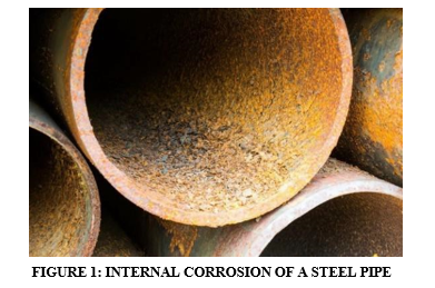
Corrosion can be attributed as the second most common cause of water main/vessel failure within Australia and New Zealand. Resulting in costly repairs as well as disruptions to critical supply of water and wastewater service, corrosion is estimated to cost the water and wastewater industry approximately $300-350 million per annum in Australia and New Zealand, with internal corrosion of pipes and vessels making up a substantial portion of this cost [3].
Challenges for Asset Owners – An Invisible Problem
Due to this type of corrosion being localised on the inside surfaces of vessels and pipes, it can often present a significant maintenance challenge for asset owners. Whilst from the outside face of the structure, it can appear to be in good condition, the corrosion activity and wall thickness loss on the inside face can be significant. In many instances, asset owners and maintenance personnel are unaware of the damaging rates of corrosion to their pipe or vessel until such a time that they eventually rupture.
As such, the presence of internal corrosion can only be identified through either specialised inspection equipment such as Remote Operated Vehicles (ROV’s) and Pipeline Inspection Gauges (PIGS) or through non-destructive testing techniques such as Ultrasonic Thickness Testing (UTT). Whilst these techniques can be effective at monitoring the internal condition of a pipeline or vessel, they require complex equipment and highly trained and experienced operators to conduct the inspection and correctly interpret the results.
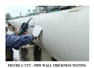
When considering these factors, it can be seen that the implications of internal pipeline/vessel corrosion can be significant if no suitable mitigation strategies are implemented. In particular due to the challenges faced to identify the extent and severity of the corrosion and the subsequent risk of unexpected rupture of the asset – resulting in unplanned outages, costly repairs and disruption of services.
Mitigation Strategies
For the reasons described above, the mitigation and control of internal corrosion is best addressed using preventative measures. This can present challenges as it will require a proactive approach on behalf of asset owners as well as the allocation of capital expenditure, which may not be readily accessible or prioritised. Nonetheless, the corrosion of internal surfaces of pipes and vessels can be controlled using a number of commonly used mitigation strategies.
Coating/ Lining Systems
Coatings and linings can be used as a cost effective, “primary protection” system to prevent internal corrosion from occurring. As they can be incorporated in the manufacturing or construction processes of the vessel/pipe, they are effective from the beginning stages of an asset’s lifecycle. There are two types of coating/lining systems that are most commonly adopted for vessels/pipelines.
Barrier Protection Coatings – Barrier protection coatings, such as epoxy resin coatings, fusion bonded epoxy linings, and polyurethane coatings are used in the water and wastewater industry as a means of providing internal corrosion protection of the steel surface by providing an isolating layer (coating) between the steel and the electrolyte (water). They are generally made up of a non-conductive, impervious material, that provides high abrasion resistance and resistance to chemical attack, thus making them a high-quality, low-cost solution.[4]
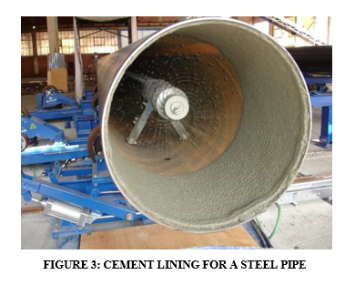
Cementitious Linings – Cement mortar linings are often used in water distribution piping and serve to create a high pH (alkaline) environment between the electrolyte and the pipe surface. The high alkalinity of the cement material will maintain ferric materials (steel, cast iron, etc) in a passive state – thus reducing their susceptibility to corrosion. Cementitious linings have a long and proven history of use and are used all over the world [5]. They are however susceptible to certain types of chemical attack (such as H2S attack), are difficult to repair once damaged, and are relatively brittle (if drilled or cut).
In addition to the above, cement lining systems are applied using a centrifugal rolling process, where pipe segments are rotated at high speeds to ensure even application and sound compaction of the mortar. As such, once pipe networks are in service, cement lining is no longer a viable option [6].
Cathodic Protection
Whilst lining systems are the most cost-effective primary protection system, they will still be at risk of corrosion at defect locations within the coating. As such, to provide greater protection against degradation, internal cathodic protection systems can be used. These will work with the active surface of the anode material being immersed within the electrolyte of the vessel whilst electrically isolated from the actual steel surface. The current will be distributed through the electrolyte (water in the vessel) and provide additional corrosion protection at the locations of the submerged coating defects [7].
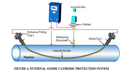
Cathodic protection is a very effective method to prevent corrosion of internal surfaces, however it can present challenges for asset owners and practitioners to ensure that it is properly designed, installed, and maintained. In addition to this, for fully enclosed vessels (such as pipes and condensers), it can be very challenging to install and extract the anodes and reference electrodes without taking the equipment off-line, isolating it and draining it down.
Corrosion Inhibitors
Corrosion inhibitors commonly work using the same mechanism as lining systems, by creating a barrier between the metal surface and the corrosive environment. When used, they are added into the liquid or gas that makes up the contents of the pipe/vessel and prevent either the oxidation of the metal surface (anodic inhibitors) or the reduction of the oxygen at the metal surface (cathodic inhibitors). Their usage and efficacy are dependent upon the type of metal used, the corrosivity of the environment and the application requirements [2]. Whilst they can prove to be very effective in many instances, they have a limited effective life once added to the water and will therefore require frequent dosing. In addition, they are proven to be less effective in higher temperature environments or in waters with high flow rates/turbidity.
Project Case Study – The Bondi WRRF
For the purpose of this paper, a discussion of a recently completed project involving the retrofitting of an internal Impressed Current Cathodic Protection (ICCP) system for a sewer treatment pipe network at the Bondi Water Resource Recovery Facility (WRRF) in NSW will be undertaken.
Structure Background and History of CP
The Bondi WRRF is a wastewater management plant located in North Bondi, NSW. The plant was originally constructed in the late 1800s as an ocean outfall sewer until it was upgrade to a wastewater management facility in the 1950s. The plant has been operating in this capacity for close to 70 years and over this time has undergone multiple upgrades and extensions to service the growing population in the area [8].
As a primary treatment plant, the facility serves to filter out the majority of effluent products from wastewater via the sedimentation and filtering of solid wastes and contaminants. The process involves passing the raw wastewater effluent through a series of filtration systems to allow the discharge of “treated effluent” (Grey Water). Whilst the plant appears to have a relatively small aerial footprint, the majority of its processes and pipework lays approximately 50m below ground level in a series of underground tunnels, as shown in the figure below.
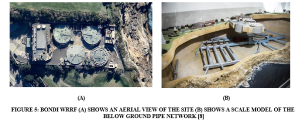
In the late 1980s, upgrade works to the facility included the installation of a new “ocean outfall” pipeline network, which served to distribute the treated effluent (“Grey Water”) to the ocean outfall tunnel approximately 2.2km from the Bondi shoreline [8]. At this time, a series of six 1000-1500mm OD mild steel pipelines were installed between the final discharge pumping system and the ocean outfall tunnel below. These pipes are the final point of the treated effluent before it is discharged offshore. The pipe network is approximately 2-3m below sea level and therefore the water within the pipes is a combination of sea water and treated effluent.
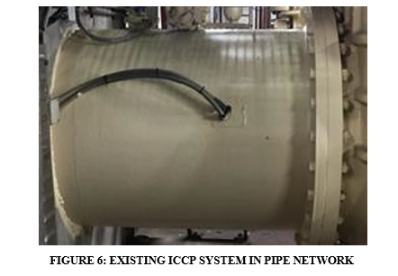
In order to address the risk of internal pipeline corrosion in this highly aggressive environment, at the time of construction an ICCP system was installed for each of the six pumps and their surrounding pipework. This system consisted of a surface mounted Platinised Titanium (Pt Ti) anode wire with a corresponding zinc reference electrode, fixed to the internal surface of each pipe via a bolted connection and adhesive bonding. Whilst this anode and reference arrangement were installed in such a way that they were inaccessible for ease of future maintenance and replacement, the pump network was originally designed with sufficient capacity in the six pumps to allow them to be separately taken offline and isolated, with the remaining five pumps maintaining the production requirements.
It must be noted, however, that since that the pump network was constructed in the late 1980s, the population of the surrounding area increased from approximately 250,000 to 750,000 people [8]. This growth in population has meant that the over the last 34 years, the operating production requirement of the plant has increased to three times its original capacity, meaning the six pumps are now required to be available for use at all times, with no ability for long duration isolations or shutdowns, more than a few hours at a time.
Nonetheless, over the original 30-year life of the cathodic protection system (1989 to 2019), routine six-monthly monitoring inspections found that it was operating satisfactorily, and sufficient cathodic protection levels were being achieved at all locations.
From 2019 onwards however, monitoring results indicated a gradual loss of protection potentials within the pipes, indicating that whilst the system was still achieving protection criteria to the Australian Standards, the internal flush mounted anodes were reaching the end of their design life and were beginning to show a reduction in protection capacity. Therefore in 2020 the asset owners, following advice from their CP monitoring contractor, decided to explore the option of upgrading the existing cathodic protection system to control the ongoing risk of future internal corrosion to this pipe network.
Optioneering Process – A Risk Based Approach
Once the decision was made to proceed with the upgrade works, a preliminary optioneering exercise was undertaken. The purpose of this activity was to analyse the possible work methodologies available to install replacement anodes and reference electrodes to the internal surfaces of the pipework. This process involved a number of risk assessment workshops undertaken with key stakeholders to discuss each available option, their benefits, cons and risks. As part of this process, the following options were discussed.
1. “Do nothing”
This option would involve the continued use of the existing anode system until they were no longer working. From this point, corrosion of the internal pipe wall would begin to propagate at an increasing rate, until reaching a point where the functional use of the pipe was significantly compromised. It was estimated that this would have an increasing risk of critical failure occurring within as little as 5 to 10 years.
2. Installation of a Flush Mounted Internal Disc Type Anode assembly.
This would have involved either isolating each individual pipe, accessing the internal face of the structure and installing an anode to the inside wall. This would be a like-for-like installation and would involve significant planning and disruption on behalf of the plant to allow each offtake pipe to be taken offline and disassembled.
The anodes themselves would be made of a flush-mounted, Mixed Metal Oxide (MMO) type disc/elliptical anode that would be fixed to the internal wall of the structure. A photo of a typical Elliptical anode can be seen in the figure below:
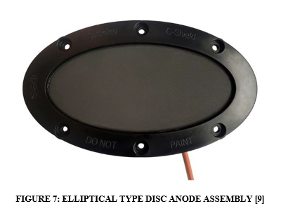
This type of installation would have to be undertaken using either of two different construction methodologies. The first would require isolating and disassembling the pipework and pump to install the anode from the inside face. This would be considered confined space works and would involve significant costs and disruptions to the plant. The second methodology would involve sending divers through the pipework via the outfall tunnel below. Whist this theoretically would be able to be undertaken without shutting down or disassembling the pipe work, it would involve considerable safety risks for the diving contractor who would be working in an enclosed environment, with limited visibility. In addition, rescue planning would be very challenging for those involved and likely involve an unacceptable level of risk to the asset owner and their contractors.
1. Retrofit Probe Type Anodes With “Hot Tapping”
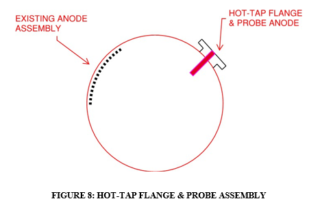
This option would involve using Hot-Tapping technology to install permanent spigots and valves at select locations on the pipe. Each of these spigots would be designed to allow a probe-type Mixed Metal Oxide/Titanium (MMO/Ti) anode to be installed within the walls of the pipe.
This hot-tap assembly would be installed on the opposite side of the pipe wall from the existing anode to ensure that the existing system remains operational and is not damaged by the coring activity. This is shown in the figure below, presenting the pipe in section view.
This option would not involve taking any plant and equipment offline and would be able to be undertaken with relatively minimal disruption to the operation of the facility.
The below table describes the risks, benefits and cons associated with each option.
TABLE 1: OPTIONEERING ASSESSMENT – RISKS, BENEFITS & CONS
| Option | Description | Risks | Benefits | Cons |
|
Do Nothing | This option would involve the continued use of the existing anode system until they are no longer working, at which point the internal walls of the pipe will be at risk of corrosion. | This option involves the substantial risk that the existing CP system stops working and pipeline corrosion propagates to the point where they are no longer functional. |
· Nil cost option in the short-term. · No disruption to plant operations in the short- term. | · Lack of protection to the pipelines. · Potential for substantial costs and disruption of plant operations in the long-term · Potentially damaging reputation for asset owner, in the long-term. |
|
Install Disc Type; Like- for-Like Anode Assembly
Isolation & Disassembly of Pipes | This option involves isolating and disassembling the pipework, and installing a flush- mounted elliptical disc anode onto the internal wall of the pipe.
This would be effectively the same as the existing anode arrangement. | This option presents a number of operational and safety related risks, including:
· Confined space access · Exposure to hazardous materials · Extended shutdown requirements for the plant; or extended period of limited plant capacity. |
· No requirement to damage/penetrate the wall of the pipe. · Proven solution that has a case-history of success in this application. |
· As with the existing anode assembly, this will be unable to be accessed for future maintenance / replacement works. · On top of contractors works, this will involve substantial mechanical works and therefore cost for asset owner. |
| Install Disc Type; Like- for-Like Anode Assembly
Installation by Commercial Divers – Swimming through Pipe network | This option would involve divers entering the pipework via the outfall tunnel and installing a flush- mounted elliptical disc anode onto the internal wall of the pipe, whilst it is in service. |
This option presents a substantial safety risk to the personnel who are required through the outfall tunnel. Issues with visibility and access limitations would make this option very high-risk for the diving contractor. |
· No requirement to damage/penetrate the wall of the pipe. · Proven solution that has a case-history of success in this application. |
· As with the existing anode assembly, this will be unable to be accessed for future maintenance / replacement works. · High-cost option. · Would involve substantial planning to ensure works are undertaken safely. |
|
Retrofit with Probe Anode | This option involves hot-tapping a flange assembly to the external face of the pipe and installing probe-type anodes, through the flange, to the internal face of the pipe walls. |
This option involves penetrating through the walls of the pipe at a number of locations and therefore creates some risk to the mechanical integrity of the pipe. | · No disruption of plant operations for installation. · Capacity to install new anodes into existing system for future maintenance works. · Eliminate the requirement for personnel to access the internal walls of the pipework. |
· Large surface area of the pipe may require 3-4 penetrations to allow sufficient anode distribution. |
When each of the above options were discussed in a workshop with representatives from asset owner and plant operations team, the decision was made to go with the final option; to install new anodes and references to the inside of the pipework via an externally mounted valve connection. It is important to note however that as this would involve creating penetrations through the wall of the pipes themselves, it was necessary to ensure that the mechanical integrity of the steel structure (wall thickness, weld condition, etc) was of sound condition.
In the event that the mechanical integrity was already compromised, creating penetrations through the wall thickness, for the purposes of hot tapping, may not be practical. As such, before the project could be formally endorsed for the next stage, a pipe condition assessment was undertaken that included magnetic particle weld inspection to verify the integrity of the existing welds as well as ultrasonic thickness testing to identify any areas of localised corrosion or wall thickness loss that may be present on the inside of the pipework.
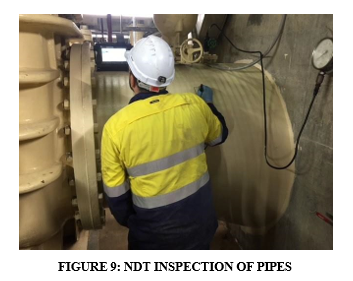
Once this inspection was completed and the mechanical integrity of the pipework was deemed satisfactory, the asset owner endorsed the project to proceed to design stage.
System Design & Planning
The design of the updated ICCP system presented a number of challenges for the engineering team. Firstly, there was very little information available on the specifics of the pipe network, excepting a limited number of as-built drawings. This meant that a number of assumptions were required to be made on critical design inputs such as the type of internal lining present (with conflicting information on as-built drawings indicating it to be either epoxy lined or cement lined), the condition of the internal coating system, the exact positioning and layout of the existing CP system componentry and other items.
In addition to this, there was no known case history of anode and reference probes being installed into a live vessel/pipe via a hot-tap valve assembly without draining down the vessel beforehand. As such, the tapped connection, valve and seal assembly would have to be designed specifically for this project to ensure the probes could be installed under pressurised conditions without loss of effluent product. Therefore, very careful planning, risk management and workshopping was required to ensure the success of this novel type of anode installation.
Cathodic Protection System Design
The project requirements for this upgraded CP system were to achieve a 25-year design life, with the “internal components” (anodes and references) able to be extracted, maintained and replaced as required without necessitating shutdown and draining of the pumps. In order to ensure these requirements were met, the following items were considered as part of the design process.
Design Current Density & Protection Criteria
As the electrolyte within the pipes was a mixture of sea water and treated effluent, it was important to consider all of the factors that may affect the current density requirements to achieve cathodic protection. In this instance, it was considered prudent to adopt a conservative design current density at all stages of the design life with the initial current density of 120 mA/m2 and an average and final of 100 mA/m2 being nominated. Whilst it was considered unlikely that this much protection current would actually be required, it would afford the system more capacity if necessary.
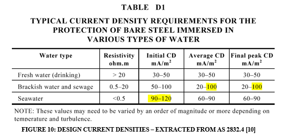
In addition, according to the report of working group 44 of the Maritime Navigation Commission [11], in aerobic conditions, protection of steel is achieved at a potential of -800 mV (with respect to an Ag/AgCl reference electrode). This value is derived from Pourbaix diagrams and is quoted in many international standards, including AS 2832.4 [10]. In anaerobic conditions however, where there is organic bacteria (such as in treated effluent), an electrical potential of -900 mV relative to the reference electrode is required to suitably combat this more aggressive form of corrosion. As the electrolyte within the pipe network at the Bondi WRRF was deemed likely to contain organic bacteria, this more conservative protection potential was adopted.
Material Selection
To achieve the project requirements, consideration had to be made on what materials would be best suited for the anodes and reference electrodes to be installed within the pipes. As described above, the electrolyte within the pipes is a mixture of treated effluent and sea water and therefore, it was imperative to ensure that the nominated materials would be suitable for use.
For the anodes, a 19mm OD Mixed Metal Oxide Titanium (MMO Ti), probe anode was specified. The anode itself would be approximately 630mm in total length, with a 150mm long active end. The remainder of the titanium rod would be encapsulated in a 420mm long non-metallic PVC Decoupler, that would extend through the valve and seal assembly and ensure that the anode was electrically isolated from the steel pipe. The length of the anode was designed such that at the end of the probe would sit approximately 300mm from the internal surface of the pipe. At the rear of the anode, a 316 SS barrel nipple would allow for anode to be secured to the seal.
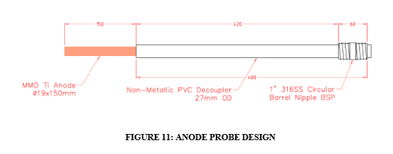
MMO Ti is commonly used in water and wastewater applications and demonstrates proven performance and longevity in aggressive environments such as the treated effluent within the pipes at the Bondi plant. In addition to this, the 19mm diameter titanium rod would provide sufficient strength and stiffness to the probe, preventing the risk of bending, deformation and damage from the flow of water within the pipes.
For the reference electrodes, a Silver/Silver Chloride (Ag/AgCl) reference electrode probe was specified. As with the anodes, these would be made up of an active end (sensor) which would sit within the pipe approximately 50mm from the steel surface. The total length of the probe would be 410mm and it would be shrouded in a high-pressure fibreglass laminate (G-10) sleeve. As with the anode probes, at the rear of the electrode, a 316 SS barrel nipple would allow for the probe to be secured to the seal.
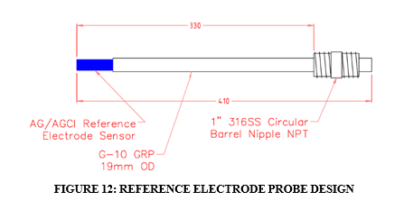
During the design phase, a number of different reference electrode types were considered including Zinc and Palladium/Palladium Chloride (Pd/PdCl2), which are known to remain stable in very high chloride environments [12]. Ag/AgCl was deemed most suitable however, due to its proven performance in seawater and high chloride environments, ease of use, handling, storage and replacement as well as its lower cost point as compared to Palladium Chloride.
Anode & Reference Electrode Positioning & Current Attenuation
To achieve optimised current distribution along the length of each pipeline, consideration was made to anode positioning. It is understood that an internal anode will evenly distribute current at a length of up to 2-3 times the diameter of the pipe, after which point, the current density will begin to drop off [13]. As such, for the Bondi pipe network, the anodes were positioned approximately 2.5m from each end of the 10m length of pipe – allowing for an average current attenuation of
2.5 times the diameter, as shown in the figure below.

The locations for installation of the reference electrodes were selected to ensure an accurate representation of the protected potentials along the length of the pipe. As such, care was taken to ensure that references were installed suitably remote from the anodes to prevent excessive interference from the protection currents.
Installation Mechanism – “Don’t Break the Seal”
As previously mentioned, there is very little/no known case history of a cathodic protection system being installed into a pipe/vessel under pressurised conditions. As such, the design, workshopping and trials of the installation mechanism and seal was of critical importance for the success of this project. For the concept design, the engineering team modelled the prototype off chemical dosing quills, which are used in industrial applications to inject chemicals inside a vessel or pipe under live conditions. Dosing quills are designed so that a probe or “spear” can be inserted through a valve assembly into a pipe or vessel and allow for chemicals to be injected into the container. Injection quills can be used in very high-pressure applications (up to 3000 psi) and are completely sealed to prevent the loss of gas or liquid product through the assembly [14].
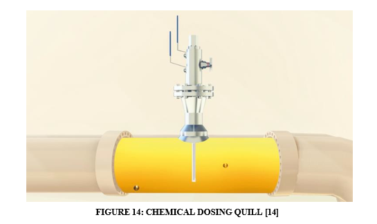
Using this model, the design team developed a removable 316 Stainless Steel seal, that could be attached to a threaded/flanged end of a ball valve. The seal would be made up of a series of O-Rings, that would be suitably sized for the 27mm OD anode sleeve and 19mm OD reference sleeve to fit perfectly inside the anulus of the component. At the pipe end of the seal, a suitably sized flange or thread would be used to allow for the device to be fitted and secured to a 316SS ball valve. At the other end of the seal, there would be a 1” threaded connection, that would allow the anode or reference to be secured via the nipple at the end of the probe, as shown in the figure below.
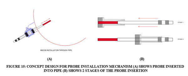
The design of the probe seal was a multi-staged process that required considerable risk assessment, engineering analysis, workshopping, trials, testing & certification by key stakeholders. As the pipe network is required to be capable of running at full capacity at all times, the implications of unplanned outages and shutdowns due to a failed seal are significant. As such, significant planning and testing was carried out before the installation mechanism would be deemed suitable for use.
Nonetheless, over a 3–4-month period, the design team worked with the asset owner and plant operators to ensure the required inspections, certifications and approvals were in place and following a comprehensive trial period, the system was endorsed for installation into the pipework.
Installation Works
Upon acceptance of the detailed design and issuance of IFC documentation, the system was installed. The installation of the anodes and references into the pipe were undertaken under live conditions, with the pumps in use at all times. In order to achieve this, whilst ensuring no leakage of effluent product, the following hot tapping procedure was undertaken:
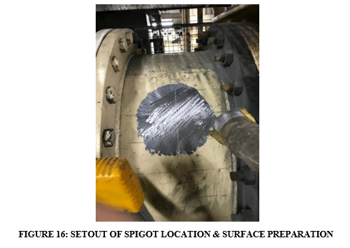
Step 1 – Setout of Spigot Connection Locations
The Setout involved locating and approving all locations for the anode/reference probes along the pipe network. Care was required to ensure that the connections would be at a suitable location to ensure ease of future serviceability and maintenance, accessibility for the insertion and extraction of the probe as well as ensuring that they would be sufficiently distant from surrounding fixings/equipment to prevent clashes/fouling with moving componentry.
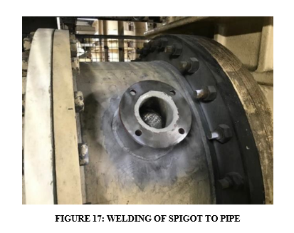
Step 2 – Welding of Spigot Connections
Following approval and acceptance of the Setout, the spigot connection was welded to the surface of the pipe. The welding was overseen by a certified welding supervisor who verified the position, type, material, output settings and temperatures of the welds. Once these welds were completed, the spigots were inspected with a 100% visual inspection and representative magnetic particle testing (MPI) by a suitably qualified NDT specialist. Approval and acceptance of the welds were of critical importance to ensure the longevity of the works and prevent the risk of future leakage or damage from low-quality workmanship.
Step 3 – Attachment of Valve & Hot-Tapping through Pipe Wall
Upon signoff and completion of the welding works, penetrations were made through the wall of the pipe via Hot-Tapping. This involved installing a valve to the spigot connection, which then had a sealed hydraulic drill attached to the other side of the valve. The drill bit used was a 40mm OD core bit that would fully retract back into the drill assembly. At the end of the drill bit was a spring activated “coupon catcher”. This meant that the drill would extend through the opened valve and cut through the pipe wall, capture the coupon, and retract back into the drill – allowing the valve to be closed and the pipe to sealed.
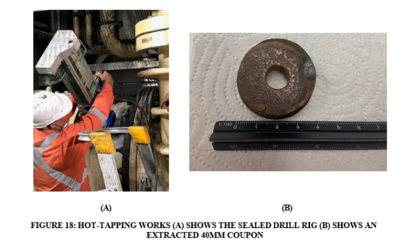
Step 4 – Installation of Seal & Probe Insertion
The final stage of the installation works was the attachment of the probe seal to the valve and the insertion of the anodes and reference electrodes into the pipe. As the installation was done under live conditions, extreme care was taken to ensure that all componentry was properly secured with a suitable Stillson pipe wrench, with Teflon Gel and tape at all threaded connections. The anodes and references were inserted slowly into the seal assembly to ensure that the active surface would not scratch or graze against the metallic surface of the valve or pipe, as shown in the figure overleaf.
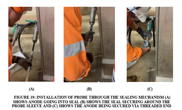
Once all anode and reference probes were secured into positions, cables connections were attached to a lug at the end of the probe and commissioning of the system could commence.
Commissioning Works
The commissioning process of the updated ICCP system was relatively simple, and was undertaken in line with the requirements of AS 2832.4 [10], with the following stages being completed:
- Pre-Energisation testing – including confirmation of loop resistances, natural potentials, verification of polarity of the electrical circuits, short circuit testing (to ensure the active end of the anode probe was not in contact with the pipe wall) and stability testing of the reference electrodes.
- Initial Energisation and Operation – including energisation of the transformer rectifier unit and application of 25% design currents at each pipe to check on and instant off values at each reference This ensures the system is polarising in the right direction (more electronegative) and informs appropriate output settings.
- System Adjustment and Polarisation – including adjustment of the output settings for each pipe and allowing the system to polarise for one week to verify output settings.
- Finalisation of System Output – including final adjustment to ensure protected potentials are achieved at all locations with the system.
Once the system settings were finalised, the cathodic protection system was left to stabilise over a two-month process proving period, where it was routinely checked for further refinement if required. It is interesting to note, that during the process proving period, an observation was made that the instant off values appeared to be influenced by the effects of the tides. As previously mentioned, the water within the pipes is a combination of treated effluent and sea water, and what became apparent during the commissioning works was that when the tide goes down, the concentration of seawater in the pipes is reduced and therefore the resistivity of the electrolyte increases. As such, what was found is that in the low tide period, the measured instant off values shifted approximately 25-30mV electropositive, as shown in the figure below.
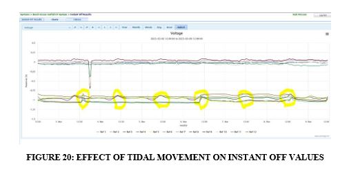
As such, due to these findings, the current output of the system was adjusted to compensate for this drop in potential to ensure the criteria of -900mV Instant OFF was achieved at all times of the day.
Conclusions
Internal corrosion of steel pipes and vessels can be a costly and disruptive issue for asset owners to manage. In many instances it can be aggressive, rapid, and difficult to identify until failures and leaks occur, and therefore appropriate mitigation strategies are required. Whilst cathodic protection systems are a proven and well-established method of controlling internal corrosion, they are commonly installed with system componentry (anodes and reference electrodes) permanently fixed to the inside faces of the structure. When critical repairs, maintenance or replacement is required, the pipe or vessel will require isolations, plant shutdowns, and drain down of areas to allow access to the inside of the structure.
Through the lens of the Bondi WRRF cathodic protection project, it can be seen that a novel system design can be adopted to allow for installation of internal componentry in a pipe or vessel without the requirement for isolations or plant shutdowns. The success of this case study demonstrates how a proactive, risk-based decision-making process could be undertaken to prevent internal corrosion to this critical asset, whilst future proofing it for the remainder of its design life.
Acknowledgments
The authors would like to acknowledge the contributions made by specialist subcontractors and consultants in their assistance with the delivery of these works.
References
- Pitting Corrosion, see: https://www.ampp.org/technical-research/impact/corrosion-basics/group-1/pitting-corrosion Last accessed 25 June 2023.
- Fontana, MG, Corrosion Engineering, McGraw Hill Education Limited, New Delhi,
- Cost of Corrosion Part 3 – Water and Wastewater see: https://membership.corrosion.com.au/blog/water-and- wastewater-part-3/ Last accessed 25 June 2023
- Water Services Association of Australia – Manual for selection and application of cured-in-place pipe (CIPP) and spray liners for use in water pipe
- Nicholas D and Moore G, From Corrosion of ferrous watermains: past performance and future prediction – a review, Corrosion and Materials 34(2) (2009) 33-40
- Cement Lined Piping – Introduction, see: https://www.piping-world.com/cement-lined-piping-introduction Last accessed 25 June 2023
- Sheir, LL, Jarman RA and Burstein GT, Corrosion Control – 3rd Edition, Butterworth Heinemann, London, 1994
- Fifty metres beneath Bondi, a stench that stings your eyes may help Sydney survive, See: https://www.smh.com.au/national/nsw/fifty-metres-beneath-bondi-a-stench-that-stings-your-eyes-may-help-sydney- survive-20220923 Last accessed25 June 2023
- ICCP, see: https://wilsonwaltoninternational.com/site/iccp/, Last Accessed 25 June 2023
- AS 4, Cathodic Protection of Metals Part 4: Internal Surfaces
- Accelerated Low Water Corrosion: Report of Working Group 44, Maritime Navigation Commission, PIANC (2005) 1-32
- How to Choose your Stelth Reference Electrode Chemistry, see: https://borin.com/how-to-choose-your-stelth- reference-electrode-chemistry, Last accessed 25 June 2023
- Guidance Notes on Cathodic Protection of Ships, American Bureau of Shipping (2017) 1-57
- Application of Chemical Injection Quills, from: https://whatispiping.com/chemical-injection-quill, Accessed June 25, 2023