Authors: S. Strudwick, JE. Pritchett.
This paper was presented at the Corrosion & Prevention 2023.
Abstract
Ceramic Thermal Insulation Coatings (C-TICs) represent a significant advancement in thermal insulation, challenging conventional insulation paradigms, which introduce the language of “K-values”. C-TICs transcend standard thermal conductivity assessments. This paper addresses the paradigm shift in the perception of Thermal Insulation Coatings (TICs) with specialised ceramics within the industry, emphasizing their proven sustainable performance beyond traditional open film conductivity metrics. C- TICs establish sealed film barriers that effectively prevent moisture and airflow ingress into the coating film. This feature significantly mitigates Corrosion Under Insulation (CUI) risks, enhances personal protection well beyond five seconds, ensures energy cost reduction, reduces carbon emissions, and sustains asset performance. Moreover, C-TICs play a crucial role in curtailing the “initial loading of heat” on surfaces, thereby limiting available thermal energy transfer. These closed film C-TICs incorporate meticulously formulated resin systems, developed by a ceramics researcher with extensive experience, including work with NASA from 1989 to 1995. These compounds are tailored to manage temperatures from 40°C to 650°C, ensuring longevity in thermal insulation applications. This paper sheds the light with practical applications of multi-ceramic thermal insulation coatings, reshaping energy management and asset protection paradigms for every industry.
Keywords: CUI corrosion under insulation, insulation, thermal insulation coatings, personnel protection, insulative coatings, process heat, solar radiant heat, TIC, C-TIC, ceramics, open film, closed film, thin film, thick film, blocking initial heat load and protecting the building envelope.
—
Introduction
When it comes to thermal insulation coatings, there’s a large range of ‘fillers’ used to promote as ‘insulation’ which use ‘air pockets’ in their structure to slow heat load and transfer. These are defined as ‘open film’ insulation coatings, which allow air transfer and rely on slowing thermal conductivity measurements of how much heat is being lost or wasted like traditional insulation materials through R and K values. For a ‘closed film’ insulation multi-ceramic (C-TICs) compounds are used that are specific for not absorbing heat. If you’re not allowing heat to transfer you can’t use old conductive values for measurement of heat transfer. The C-TICs performance, which doesn’t absorb heat yet blocks heat ‘load’ is the key. Advanced ceramics are amongst the only materials that can be engineered to endure hundreds of aggressive cycles in harsh environments while delivering clean, consistent performance. The reason is simple, they are earth materials that have been resistant to weathering. Thanks to their extreme toughness due to their structure while being light weight, resistance to high temperatures, chemicals and wear, as well as their excellent electrical properties, ceramics are able to create particularly high- performance and durable coatings products.
In today’s microchips, they contain millions of transistors and are improving our cars, phones, and refrigerators— empowering Internet searches, genetic research, and smart sensors. This process heat is dispersed and managed with organic, inert ceramics. Many other industries utilise ceramics for performance, diversity and reliability. Because of these properties, advanced ceramics play a vital role in many industries and high-temperature environments, such as electronics, metal production, power generation, and other industrial processing sectors. Ceramics are structured differently and must be chosen for specific duties. Some ceramic compounds are used to transfer heat and electrical currents while other ceramic particles are equipped to “block” heat and resist electrical transmission.
The lightweight ceramic particles blocking heat are the ones used for either “thin film” to reflect heat waves or “thick film” to block and hold heat on a surface. These ceramic compounds were evaluated on an individual basis to find which particles would work to reflect or would block heat under “use” conditions. This means that the compounds had to be blended into a wet coating and mixed with other ingredients to find which ones would continue to provide the same insulation quality performance as when in a dry state. All compounds have their technical information produced based on a dry state condition. You cannot take this dry state information of performance and expect it to work in a wet state after being blended into a paint or coating.
C-TICs boast an extensive history of field and laboratory testing spanning numerous industrial sectors and diverse global environments over the course of several decades. These closed film formulations, enriched with ceramic components, have unequivocally substantiated their insulation capabilities, resistance to Corrosion Under Insulation (CUI), and long-term durability through a well-documented history of exceptional performance. Only a handful of manufacturers have developed the proper balance of insulation compounds with ceramics and the correct resin systems to deliver performance expected by customers in oil and gas, petrochemical, power and heavy industries. However not all TICs are made equally to address the same insulation challenges. By differentiating between process and solar radiant heat, engineers can correctly specify C-TICs which are fit for purpose. As mentioned, only one known manufacturer of C-TICs to date has developed the resin formula holding the resin/ceramic system with particular ceramic compounds that can block moisture and air from reaching the metal to cause CUI while providing insulation to the surface. What is unique with this manufacturer and worth the mention here is that the resin system and ceramic blend can provide insulation from the usual 177C/350F up to 650C/1250F. This is appropriate to mention the advancement in resin/ceramic blends that have evolved over the past 18 months. Most suppliers of TICs offer only the systems up to perhaps 260C/500F stating that this is all the customers (oil/gas/industrial and even commercial) need. This is not true and to try and tell the customer that they do not need TIC systems that can reach over 260C/500F is in effect trying to “limit the customers’ expectations” which should never be the case. The customer always tells the supplier what they need and not the supplier based on their own limitations telling the customer what their limits are. In the market, the customer will hear more about “personal protection” than about energy savings or “insulation”. Why is this? Most TICs have not put in the years of trial-and-error research to find the ceramics that can work in the “wet” state to provide the
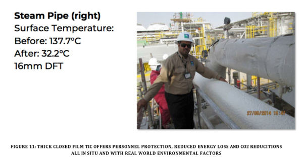
insulation factor. After they blend the dry state ceramic into a coating and it reduces or eliminates the insulation factor, it can provide a textured surface to help with burn control which is what they promote as a 5 second burn prevention. If someone fell on a pipe or exchanger, they could be there for more than 5 seconds, and this is not what you want anyway. Why not opt for true insulation to save energy and at the same time ensure you can lay on the surface for 30 minutes if you are slow to get up or injured without threat of burning.
Thick coat closed film C-TICs (1mm to 75mm) solutions for blocking and holding heat on the surface of a pipe, heat exchanger, etc to maintain heat inside the unit and increasing efficiency from as low as 40% in some operations to above 80% efficiency. This elevates the entire production of the same plant doing the same daily operation. Heat loss off the surface is the main sustainability issue addressed. Holding this heat on the surface allows the unit to achieve it’s goal so that this heat can be used as intended which reduces CO2 emissions, dramatically reduces energy lost and ensures permanent personnel safety at any temperature. This distinction between thin and thick closed film C-TICs can also help determine the correct application thickness, method and investment. The choice of thickness and type of insulative coating is critical for the end users to receive the expected benefits they wish to achieve in their specific project and environment.
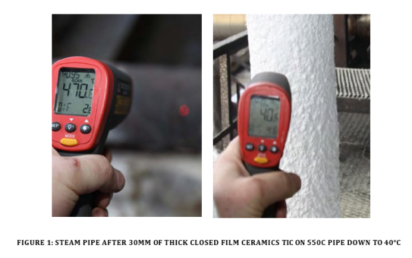
There are notable efficiency increases without changing anything other than coating thickness on a unit with a material that ‘holds’ heat on the surface are available and it also moves away from the risk of traditional jacketing insulation that has a direct link with CUI. Open film TIC materials (standard insulation materials) offering R or K values are not designed to ‘hold’ heat on a surface of a substrate. These materials are designed to ‘slow’ or ‘resist’ the loss of heat off the surface until they reach ‘heat flux’ or full of heat themselves. The long proven technology of closed films ‘holding heat on the surface’ are more efficient with the added quality of resisting or blocking air and moisture which causes CUI all with the one coating system. Energy efficiency with proven CUI and personnel protection in a single closed film C-TIC is a game changer. Recently in the USA, the oil/gas sector asked a laboratory to establish a testing procedure to verify if a TIC delivered manufacturer’s claimed performance. This is a great idea, BUT, given the limitations of the TIC suppliers, the suppliers were trying to limit the heat levels and insulation expectations of the test protocols for the customers. This is where the one supplier of the higher and new technologies for heat levels and CUI controlling systems stepped in to open this expectation up to match what the customers (oil, gas and industrial) needed. This is important to understand when the customers have needs
that most suppliers cannot meet. Understand that the latest technology has been developed to cover these needs, which requires finding the supplier that can provide.
In the quest for C-TICs optimisation, a variety of closed film multi-ceramic based coatings are now a proven alternative to conventional jacket and are distinctly different to acrylic based fillers or open film TICs. Closed film multi-ceramic C-TICs using acrylic hybrid resin systems provide energy efficiency to infrastructure in an age of sustainability which includes measurable savings for both maintenance costs, energy costs, staff well being, CUI protection due to the resin systems and the environment. Example: During a shut down and the jacket is removed, the wrap is hanging loose and limp off the pipe. This is not insulating on any level.
In the quest for C-TICs optimisation, a variety of closed film multi-ceramic based coatings are now a proven alternative to conventional jacket and are distinctly different to acrylic based fillers or open film TICs. Closed film multi-ceramic C-TICs using acrylic hybrid resin systems provide energy efficiency to infrastructure in an age of sustainability which includes measurable savings for both maintenance costs, energy costs, staff well being, CUI protection due to the resin systems and the environment. Example: During a shut down and the jacket is removed, the wrap is hanging loose and limp off the pipe. This is not insulating on any level.
Formulation
According to Polaris Market Research, the worldwide TIC market is anticipated to reach around $13,189 million by 2026 [1]. In 2017, the acrylic segment dominated the global market in revenue, with Asia Pacific accounting for the majority share of the global thermal insulation coating market [2] While open film acrylic formulations dominate sales, other high performance options are also available for specialised applications and climatic conditions. Where the acrylic formulations have temperature limitations, third generation polysiloxanes can be applied on both elevated and refrigerated temperatures of -60 to 400C (-76 to 752F) [3]. As the market awareness for TICs expands, awareness of specialise closed film multi-ceramics formulations are proving their high performance properties across many sectors. Therefore, specifying the proper formulation for the specific asset is the second vital step in selecting a TIC, which is fit for purpose.
The mainstream contribution to insulation properties is not from the binder but from incorporating high loadings of test proven ceramic compounds with low thermal conductivities such as hollow glass and ceramic microspheres, silica aerogel, and other compounds such as perlite. In particular, effective fillers have large amounts of still air trapped in their voids and pores [4]. These formulations are commonly used and go to the heart of open film TICs and their conductivity. In the latest technology, the air-trapped filler is not used as much due to the compounds that physically do not have the density to absorb heat and hold it. With its reaction, the heat cannot load effectively and transfer as it does with air pocket materials.
Originally much of what is known about ceramic compounds was limited to space travel technology or minor R&D work performed by major corporations associated solely with their own raw materials. Beginning in 1988, one company began research to determine what type of ceramic compounds could perform to block the absorption of heat and therefore block heat transfer with an initial focus on solar heat transfer. As research continued, design characteristics became clear as to the ceramics and their properties which includes:
- Material make up
- Crystalline structure (not understood by the mass suppliers)
- Processed method (not understood by the mass suppliers)
- Size
- Density
These characteristics provided the best possible heat resistance, emissivity and heat blocking ability. Since form, size and type of compound had never been studied for the purpose of heat control in a commercial TIC form, finding and testing individual ceramic compounds became the focal point to find all possibilities available. As research developed, crystalline structures was noticed to contribute to a compound’s ability to refract heat waves from both sun radiation and mechanical heat sources. Density was found to be a critical component in heat absorption and loading. Size was found to be extremely important in the effort to block particular radiation heat waves.
During the development period of research, in order to find the correct compounds, engineering studies were being performed to determine which radiation heat waves were the most concentrated representing the total heat load from sun radiation, which included radiation, convection and conductive heat. From this research of over 4000 ceramics (since 1989), specific compounds were selected to perform the blocking of these heat waves for the design of the closed film C-TIC. Designing a multi-ceramics closed film/thin film coating to block the studied heat waves provides the scope and goal for blocking a minimum of 96.1% of the ‘heat load’ from radiation waves.
Given the introduction of ceramic compounds created for the purpose of C-TICs insulation more than forty years ago, architects writing specifications have seen very positive results in their insulation affects. Since the ceramics are usually carried within resin systems having a low permeability, the effect of airflow that cancels the insulation impact on air filled materials is eliminated. Significantly the timing of heat transfer through air pockets of open film is eliminated, and the effect of moisture load into the material (that immediately cancels the W/mK number and R or K values) is eliminated as well. To understand the desire to utilise thermal conductivity terminology we need to understand its origins.
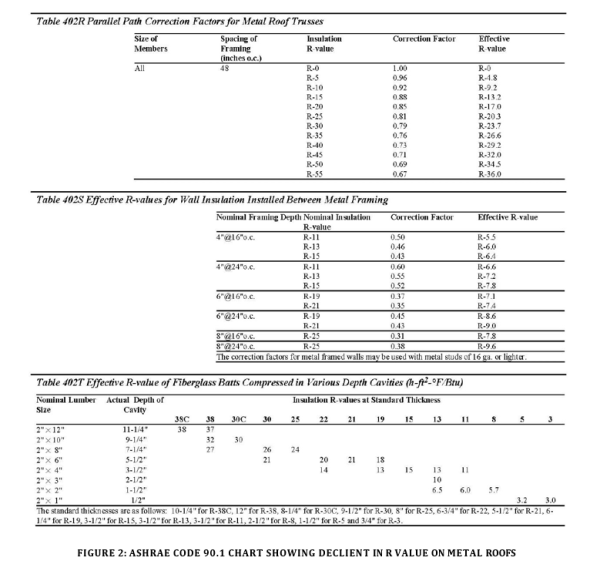
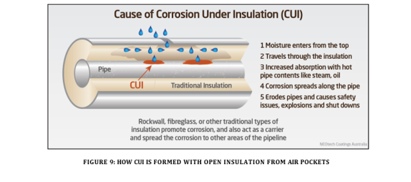
Air flow and moisture load are two elements that are present in all atmospheric conditions and immediately affect the performance of standard or traditional bulk insulation materials and are the cause of CUI. This means that any W/mK numbers and R or K values calculated for these materials (fiberglass/rock wool, cellulose etc) in laboratory testing are useless outside of the laboratory conditions, as tested and verified by Georgia Tech University in Georgia, USA. In addition to the negative affect convection (air flows) and humidity conditions will immediately have negative adverse effects on these
These traditional insulation materials are only effective as presented by lab testing at 24C if installed at the full 150mm thickness and placed in the identical environment as tested. As reported by the ASHRAE (American Society of Heating, Refrigerating and Air-Conditioning Engineers) code group in the U.S.; when fibreglass (one of the air filled materials) is used over metal structures or framing of any kind, the R21 value rated material is immediately reduced to a R value of 7.4 because the material does not and cannot effectively cover the metal surfaces, supports and connections to effectively provide the insulation value throughout the wall or roofing. Add moisture to the mix and the thermal efficiency deceases even more.
Due to the entrenched R value education and language from the 1970s, it’s been assumed that measuring thermal conductivity based on R values is the only way to measure heat transfer. The new TIC open film coatings have adopted this traditional heat transfer measurement into their coating language because they have air ‘fillers’, like traditional insulation and utilised K values or lambda as their new language but really it’s adopting the old narrative in a new world.
Heat Load
Heat load calculations traditionally are for figuring out the amount of heat needed to keep an enclosure within the desired temperature range [5]. If heat from internal (ie pipe) or external (ie solar) influence pushes heat into and through a material it will load fully absorb and load all the heat causing it to eventually reach a heat flux. If radiated solar heat trying to enter a structure can be reduced significantly as a closed film C-TIC does, it reduces the amount of heat available for transfer and, therefore, acts to control the conduction of heat and heat load and becomes a non-conductor.
With less heat load available for transfer, there is less heat available for conduction into the asset. In a pipe situation, the majority of heat load is controlled and blocked on the initial surface, no R or K value (that absorbs and accepts “heat flux” as the goal) is required for closed film ceramics TICs. Blocking the initial heat load is the ‘key’ to controlling heat transfer and flow into or out of a structure like an airflow barrier. Mainstream insulation materials or open film ‘air-filled’ materials depend solely on slowing or resisting absorbed heat for a given period of time and then allowing it through to transfer at a controlled rate until full (heat flux is reached). These materials aren’t designed to stop the loading and transferring heat load and therefore work on conductive measurements of R and K values.
The process works in reverse endeavouring to hold heat on a surface. Insulation that also covers hot pipes, furnaces, boilers and all types of hot surfaces or circumstances to block the heat transfer. This type of closed film/thick film C-TIC requires different ceramic blends for a coating to be effective in this type of requirement. To suggest that one type of ceramic or compound can do all jobs (reflecting radiation waves and/or “holding” heat on a surface to prevent heat loss) regardless of the heat level, is a totally un-informed view of these types of insulation technologies. Different ceramic compounds carried by specific resin systems must be designed for specific thin and thick film insulation systems.
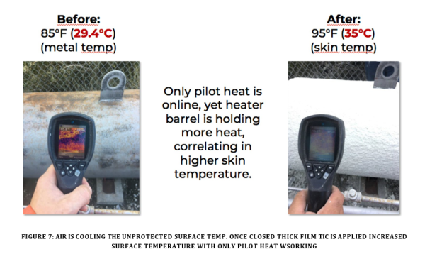
Research was performed on all ceramic compounds to find the ones that could block heat transfer in a ‘catch and hold’ method. Instead of trying to reflect or repel heat from a hot pipe surface back into the pipe, which would enjoy very limited success because of the physics involved (cooler heat cannot be thrown back to higher heat), ceramics were found that resisted the loading of heat from the pipe surface. The heat loading into the pipe surface from the interior of the pipe is stabilized by ceramic compounds that physically are resistant to absorption of heat causing the pipe surface heat to stall from leaving the surface to the atmosphere and be held on the surface
matching the interior heat level. This is why for thick film, heat holding insulation coatings, you never want to know the temperature of the pipe surface, you “must” know the operating temperature inside the pipe to be able to judge the thickness required to meet the customers requirement.
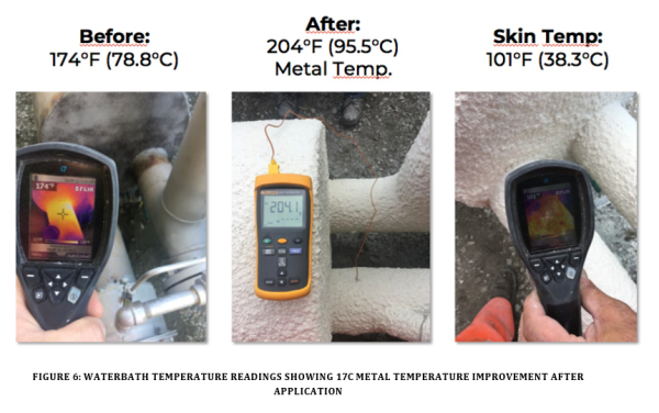
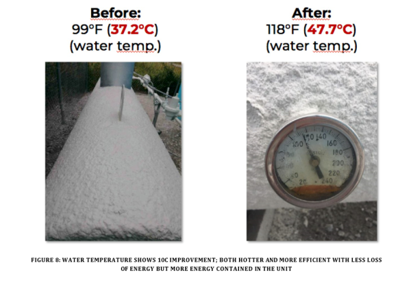
This increases the pressure inside the pipe or vessel because the exterior surface heat is held thereby causing the interior to actually contain more of the produced heat energy, increasing the pressure, as found in steam pipes or bath heaters. This pressure increases the heat level until a heat equilibrium is reached between the interior operating temperature and exterior temperature of the pipe. When the heat is trapped, the pressure will increase, which will in turn elevate to higher temperature levels than previously experienced. The overall effect is a reduction in the fuel consumed to maintain the heat level inside the pipe or vessel because of the limited loss of heat off the surface. Thus making it more sustainable.
Again, open insulation, regardless of their properties either as fibreglass, glass spheres or gel materials cannot hold the initial surface heat load of the pipe or vessel like a multi-ceramics closed film/thick film TIC. This heat always migrates and transfers to the cooler side of the materials.
Air is assumed to be the best insulation on earth. The open air-filled insulation materials can act as a structure to hold your hand away from the hot surface so that you will not be burned, but the real insulation effect (considering moisture load and air movement inside the materials), the insulation utilised to actually hold heat without dissipation on the surface is not available to this type materials as stated by the R or K value testing procedure stating the test operates until the material reaches “heat flux” or fully loaded, then the test is terminated.
Insulative Coatings
Traditionally its believed that TICs are functional coatings which inhibit the transfer of heat by slowing down the conduction mechanism via their low thermal conductivity [4]. While this is the common view for open film TICs, we propose a coatings technology that focuses on resistance to heat load thus non-conductive properties with multi-ceramics closed film in thin or thick film C-TICs. For the purposes of this paper, we will differentiate between process heat applications which generally require a thicker film application above 1mm DFT, compared to solar radiation applications which generally require a thin film application of coating below 0.25mm DFT. Specifying the correct type of insulative coating is critical to selecting a closed film ceramics TIC which is fit for purpose.
Insulation used to limit the heat lost or gain from the environment is a very common type of heat conservation. Certain ASTM tests related to conduction and reflectivity now allow for more detailed testing of various types of insulative coatings. Test Methods to Evaluate Thermal Properties and Performance of Insulative Coatings NACE SP21431-2020 [6] attempts to build on industry consensus for testing used to evaluate the performance of different types of insulative coatings.
It has been learned from studies performed on testing procedures created for testing insulation materials, that results are adversely affected by atmospheric conditions when used in the field. Carefully chosen ceramic compounds in closed film (thin and thick film) C-TICs are designed to work regardless of the atmospheric conditions found in all field applications. The ceramic compounds were chosen from extensive research on over 4000 compounds to determine which type of heat flow could be blocked. Ceramics selected were mixed with other effective compounds to provide a comprehensive reflection of the three sun radiation waves (UV, Short or visual light and IR or long wave) of heat from the surface (thin film) or blocking heat escape (thick film) from a hot surface.
Thin Film – Insulative Coatings for Solar Radiant Barrier
For any coating to be represented as a ‘reflective’ thin film C-TIC coating that can block ‘heat’ could mean that it only blocks visual light, which is 44% of the total radiation heat, received from the sun. Radiation heat is broken down into three separate nanowaves: UV 3%, Visual Light 44% (short wave) and Infrared 53% (long wave). Any coating that represents any as a thermal ‘insulation’ coating and doesn’t block all three of these waves is not representing the scope of blocking heat absorption and transfer. SUPER THERM@ is a thin closed film ceramics insulation coating made up of 4 ceramics which block a total of 96.1% of total solar heat trying to absorb from the sun radiation into the surface of the coating film as opposed to “white” paint that only reflect visual light bounce and not necessarily all the heat as observed on a white car bonnet that is still hot on a 32°C day. Why is that? The white paint cannot block all the heat from the Visual wave and does not have any effect with IR (53% of the heat) into the metal under it, resulting in a surface that will burn your hand when touched.
NACE SP 21431-2020 [6] lists ASTM E408 and ASTM E903, which calculate a coating’s emissivity and reflectivity. Reflectivity and emissivity deal with radiation, which is completely different from conduction, related to other forms of heat transfer. Where conduction is measuring ‘how fast’ heat moves, testing related to emissivity and reflectivity is measuring ‘how much’ heat is absorbed and then released but not transferred. It is important to note that ASTM E4087 and E9038 are known as a single light beam bounce. The building industry through the CRRC (Cool Roof Rating Council) and Energy Star uses a different version of these tests (ASTM C1371), considered more representative when testing emissivity and reflectivity on structures such as roofing yet they don’t consider conductivity as part of their measurements.
These tests are ASTM C1371 for emissivity and ASTM C1549 for reflectivity. Depending on the asset to be protected, some organisations will prefer to specify testing from CRRC. Note that reflectivity testing is measuring short wave visual light and does not consider all nanowaves of heat including all the infrared radiation range absorbed. When reviewing these tests, additional ASTM, laboratory and field testing is needed to fully understand the ability of a closed/thin film TIC coating to repel ‘actual heat’ from the surface facing the sun, not just the visual light bounce.
Some thin open film C-TICs coatings are water-based acrylics, comprised of air filled ceramic and silica beads held in suspension by an acrylic binder. These coatings rely on testing for thermal conductivity, again about the air transfer through the coating unlike the close film TIC coatings, which are designed, to block heat with no air transfer in the film. Additional note is that when using air bubbles or spheres, the loading must be large to obtain a good result causing an overload of the resin system that can weather out faster.
Thick Film – Insulative Coatings for Process Heat Loss Mitigation
NACE SP 21431-20203 lists ASTM C1776, which measures Thermal Conduction. The NAIMA (North American Insulation Manufacturers Association) has used ASTM C177 or C518 to establish an R-value by sandwiching conventional insulation materials between a hot plate at 24C (75F) and a cold plate at -3.89°C (25°F) and registering how much time it takes to raise the cold side by 1 degree F which is an open air method of measuring heat transfer.
In essence, the R-value is a time-based formula. It calculates how long it takes for the heat to transfer from point A to point B through the insulation material. However, for insulative coatings, ASTM C177 only measures thermal conduction in a steady state equation. Therefore, comparisons between open conventional insulation and open insulative coatings are not appropriate due to the fact that TICs are typically not thicker than 25.4mm (1 inch). The traditional form of ASTM C177 is the preferred method for measuring thermal conduction for insulative coatings, since insulative coatings do not have an R-value.
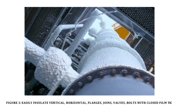
The K value is basically a shortened phrase for thermal conductivity, which is the time rate that heat steadily flows through a unit that is induced by the unit temperature in a direction that is perpendicular to the area [9]. The lambda value, also portrayed as ‘K value’ or ‘λ value’, measures a product’s thermal conductivity in units of W/mK [7].
Coatings companies are endeavouring to develop new TICs with terminology of thermal conductive lambda and K values. Yet industry awareness of TIC’s that offer proven sustainability benefits need to extend beyond the old insulation conductivity language into the new realm of closed film insulation coatings that block and hold heat on the surface (thick film). In the end whether you’re talking R, K or lambda it’s the old terminology about thermal conductivity or slowing heat transfer through a material…or in other words slowing heat loss yet once the heat is through, it reaches heat flux. It is assumed that most insulation coatings are recommended for surfaces with service temperatures up to approximately 177C (350F) [4], however we know closed film multi-ceramics formulas (thick film, close film) will manage up to 650C or a 267% improvement over the assumed temperature while still maintaining personnel protection, giving real insulation effect and resisting CUI all in one coating.
Thick closed film testing
With the development of non-conductive closed/thick film thermal insulation multi-ceramics coating products similar to HOT PIPE COATING (HPC) up to 204C/400F, INTERMEDIATE 204C/400F up to 538C/1000F and HT 538C/1000F up to 677C/1250F, that have a different layering of ceramic compounds based on resisting absorption and the loading of heat and not reflection, the key to actually insulating the pipe or vessel was found to be fast, easy and extremely more effective. Unlike the air-filled or open insulation materials, it is not a measurement of how much or how fast the surface heat is dissipating through the material, thereby requiring great thicknesses. The effect is to resist the initial heat load of heat from the surface by blocking the absorption of the heat that could be transferred to the exterior surface of the coating. This is actual insulation.
In the testing procedures of R or K values, the material is tested for its individual heat ‘resistance’ performance value specific to that material or how fast the heat loads and transfers through the material to the cool side. This BTU (British Thermal Units) or W/mK is then divided into one particular thickness to find the relating R or K value. Closed film multi-ceramics TICs have been tested for these values at 0.071 W/mK per ASTM C177 and/or 0.06 kcal/m-h-degC or 0.07 W/m-degC. This is where you must understand how this testing measurement works. In the standard insulation materials using the ASTM C177 or C518 for conduction, they are experiencing all the heat loading and transferring . In the thick/closed film coating, the measurement of the heat load is “only” the amount of heat that “ could b e loaded” and then this limited amount of heat is judged on how fast it moves through the coating film giving the W/mK rating. Remember that not all the heat loaded. The established testing procedures “assumes” all the heat was loaded and measured based on standard open air pocket materials. Therefore, the rated W/mK number produced by this test on the thick film closed formula never considered the resisted or unloaded heat, it only recorded the small amount of heat that did pass through as the W/mK. This is a huge difference in actual performance. But, as it is today, we are controlled by the standard test procedures dictated by the standard insulation material groups that helped establish the test procedures when being on the ASTM committee developing the tests.
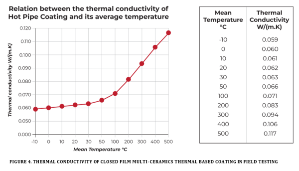
The closed film C-TIC was taken through a layering of heat levels to show the change in heat flow resistance in actual use, not in a lab. Doctorates in Europe ran the calculations from lab studies and related the findings to actual field use. As in all insulating materials, hot pipe coating performs the best at low temperatures. Fibreglass insulation at 20C has a thermal conductivity rating of 0.04W/(m.K). Above a mean temperature of 350°C the closed film C-TIC had a thermal conductivity passing 0.1 W/(m.K). The effect on the surface temperature and the heat loss of 1 metre run steel pipe thus depends on the temperature of the fluid in the pipe, the insulation thickness applied, the diametre of the pipe and the fact of the pipe hangs inside or outside.
Only to illustrate the effect of closed film C-TIC, we calculated the reduction in heat loss per metre run for a steel pipe with an exterior diameter of 10 cm, hung in an environment with an effective temperature of 20°C. The pipe transports a 350°C hot fluid and is insulated with a 1cm thick layer of coating. Without coating, the heat loss touches 3409 W/m. With closed film C-TIC it diminishes to 776 W/m, i.e. a decrease with 77.3%. The average thermal conductivity in the coating then reaches 0.088 W/(m.K).
In the testing and results for the air-filled materials such as fiberglass, rock wool and others, the W/mK number will appear only at the 24C/75F testing level. Their numbers will be in the range of 0.04. Compared to the closed film C-TIC at 0.062, these air-filled materials appear to show greater thermal blocking ability than that of closed film C-TIC, but this is based purely upon lab performance without factoring air flow and humidity influences. Therefore, in actual use, these numbers are completely invalidated when air begins to enter and flow through the open material or open film, creating a faster release of the heat and causing the resistance to drop dramatically compared with a closed film C-TIC. Remember: all standard insulation materials are only tested at 24C/75F as their only tested temperature. Anything temperature over the 24C/75F is not validated. Just for the record: As an example of a US government agency rejecting the idea that 24C/75F is appropriate for any climate: “given the temperature differences throughout the country, no one temperature is likely to be sufficiently representative of consumer experiences” …. Additionally, the testing of only one thickness (usually 3 inches) and achieving the R value then stating this value is multiplied out to additional thicknesses is not correct as stated by the same agency.
At the same time, due to moisture (humidity and environment) loading into the standard material makes heat travel faster through the material to be loss or gained. The closed film C-TIC with ceramics resists moisture load and air passage to reduce heat transfer and CUI. With the combination of air flowing into and through the open film material insulation and the induction of moisture, the standard insulation material cannot provide the presented W/mK value as of the day it is applied in the field. On the other hand, the uniquely selected closed film thermal insulation ceramic compound coatings can and will perform as stated because they were tested for water permeability to show the ability to resist moisture load and air flow.
The ability to stabilise the environmental effects over the coating surface in which they operate allows them to function as presented from testing results in the field through actual use and consistent performance in situ as expected. This is why closed film C-TICs will control ‘corrosion under insulation’ (CUI) by prohibiting the moisture load and air flows under the coatings to corrode the surfaces coated.
In as much as heat always goes to cold, open film and standard materials base the insulation effect on only slowing down the transmission of heat to the cold, the heat still loads and slowly transfers until it reaches “heat flux” or fully loaded. It doesn’t block it. As to the closed coating system, heat is resisted at the initial load point, reducing the quantity of heat available for transfer. The properties of non-conductive insulation closed/ thick film ceramics are completely different where they resist the absorption of the surface heat of the pipes or tanks and contains this heat on the surface of the pipe or tank to provide the insulation, thereby reducing energy loss to the atmosphere and giving personnel protection.
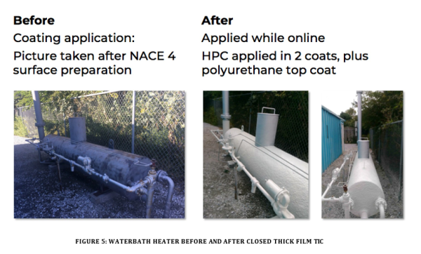
Case Study – Water Bath Heater
Water Bath Heater – 24” Diameter, 10’ Length – 79.4°C
Challenges: Corrosion Under Insulation. Failure of insulation materials, due to moisture penetration.
Solution: 10-12mm or ½ inch dry film of waterborne, non-toxic, non-flammable, ceramic cross linked acrylic based insulation coating applied directly to water bath heaters while in operation.
Desired Results: Corrosion under insulation protection. Significant heat loss reduction. No space for pests and vermin to hide in.
Equipment: Graco GTX EX Texture Sprayer
Environmental Factors
As described, climate is another important factor when specifying TICs. An oil and gas facility in Siberia differs from Saudi Arabia and Australia in evaluating the requirements for insulative coatings. A colder climate will use thicker film, process heat related insulative coatings as opposed to solar radiation barrier coatings. Cold climates facilities are less concerned with solar radiation heat as opposed to heat loss mitigation. Conversely, the hot climate conditions will generally utilise more thin film solar radiation barrier coatings and while they may use thick film insulative coatings they will generally require less thickness as compared to the colder climates. Environmental factors also impact curing rates.
The given parameters of BTU or W/mK heat transfer have been critically challenged according to how the numbers are interpreted by the standard nominal laboratory test procedures. The lab procedures established created unrealistic test parameters, such as determining a near ‘0’ humidity environment, a single pre-set temperature (obviously established for the optimal heat resistance of air filled materials), and zero air flow. The testing established for all air-filled insulation materials does not and will not relate in any practical way to the actual atmospheric conditions in any of the environments known throughout the world.
Additional Options for Application
There are scenarios where a conventional insulation jacket and a solar radiant barrier can be used together to create a longer lasting, higher performing insulation system. The exterior of existing jacket insulation on cold pipes for example can be top coated with a thin film solar radiant barrier to reduce the “initial heat load” and heat transfer into the cooler side. Another option is to replace the conventional jacket insulation with a thick film TIC and then topcoat the thick film with a thin closed film that blocks out most of the initial heat load and therefore reduces the amount of heat available for transfer to the non-conduction resistant coating. The thin film reduces solar heat load, while the thick film slows heat transfer. Recent experiments have also been conducted on thick film insulative coatings for below grade piping, which can reduce cathodic shielding, when paired with a fusion bonded epoxy primer and water resistant topcoat.
Corrosion Under Insulation
When corrosion under insulation is the primary concern, a thick closed film C-TIC is recommended. Thin closed film C-TIC simply does not have the same type of body and temperature resistance as compared to the thick film C- TIC that are generally designed for CUI. ASTM B117 can be used to test for corrosion resistance of C-TIC, which have not yet been placed into service. Once in service at elevated temperatures, that is above 50°C, the corrosion mechanisms may be different and not suitable for atmospheric coatings.
Personnel Protection
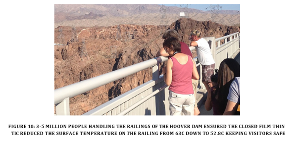
Traditionally the process systems selected for personal protection insulation are operating at temperatures that could cause hot or cold burns, and have been insulated with a physical insulation system either traditional jacketed insulation or mesh type guarding [8]. When personnel protection or safe to touch is the primary concern, a thick film C-TIC is recommended, however even with radiational solar heat a thin film insulation coating can be used as a safe to touch solution. In the picture below, SUPER THERM@ coating applied at only 250 microns/10 mils dry was selected from a group of reflective or insulative coatings after the engineering tested the ability of each coating to perform. All other reflective coatings only reduced the surface temperature of the handrail by a few degree still at 63C/146F, while the thin film C-TIC reduced the surface temperature to within 2 degrees of ambient providing a safe to touch by the millions of visitors hanging their arms over the railing while viewing the hoover dam. There was a two-year review for surface heat level testing and another review at 12 years with the performance remaining the same as when newly applied.
C1055 [10] allows for a 5 second touch rule up to 59C (138F) which is the start of a 1st degree burn. Human burn hazard is used in conjunction with ASTM C1057 as a method of determining skin contact temperature from a heated surface. The temperature limits determined when using this test method are specific for each coating tested at a particular thickness and substrate temperature. A standardised test method can validate the temperature limits of a coating used for personnel protection, and enable direct comparison of its performance.
Any coating that works just on the principle of 5 seconds safe to touch isn’t actually performing as a true thermal insulation coating nor offering realistic personal protection. Coatings that block the heat on the surface or reflect the radiational solar heat for an indefinite time are truly both insulating and protecting. If at 59°C a human can only withstand 5 seconds isn’t ‘safe’. In that case you can give your employees gloves. What happens in the scenario of someone falls and injures themselves on a pipe or other operational machinery…5 seconds isn’t safe!
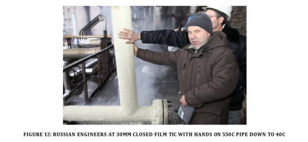
It is expected that thick thermal insulative coatings are working to replace conventional insulating materials and mesh guards. Superior closed film thermal insulation coatings address both total energy efficiency and low thermal conductivity from a 250 microns thickness from radiation heat up to 30mm for 600°C+ for heat on pipes etc and offer personnel protection. Naturally depending on the heat and personal protection needs will depend on the thickness required.
Assuming no solar influence, the surface temperature of a coated surface is dependent on two coating parameters including emissivity and thickness. While other companies may also include thermal conductivity in their safe to touch factors, our experience is not the same. This means those products don’t control the heat loss and not confident in their coating’s capability to give permanent safety protection. Discussion of K values or thermal conductivity as the goal shouldn’t exist, the goal is to hold the heat on the surface which is achieved with the right ceramics and resins formulations that have high emissivity capabilities pushing the heat back to the source.
Some researchers/companies will include the effects of solar radiation as part of the thermal insulation coatings influence along with thermal conductivity; the reality is formulations that have high emissivity won’t allow solar radiation or thermal conductivity to be an influence on surface temperatures. That is, if the TIC formulation isn’t able to block heat, but slow it, then their need to discuss these extra thermal influences makes sense.
Safe to touch really hides behind a time dependent function for many open film TICs because their coatings won’t hold the heat out for very long. There are also K value numbers rated for the filler only and not the total binder agent such as acrylic. The theory behind ‘safe touch’ properties relies on thermal conductivity principles. A coating for personnel protection using closed film ceramics which has outstanding emissivity properties pushes the heat back to the source and blocking heat load, keeping all humans safe, always and not just for 5 seconds.
Trade Names
HOT PIPE COATING (HPC)
HOT SURFACE COATING (HSC)
SUPER THERM
Conclusions
The newer alternative generation of closed thin and thick film multi-ceramic thermal insulation coatings provide insulation without being affected by moisture and airflow. They are designed to block and contain heat at the surface to resist heat loss or heat gain. Preventing moisture and air entering the coating film therefore provides a dramatic decrease in corrosion under insulation, which is a major cause of corrosion challenges in the field. Keeping heat at the surface also provides much more efficient and sustainable infrastructure through less maintenance, reduced CO2 emissions, and reduced costs while giving outstanding and permanent employee protection.
Selecting the proper ceramic thermal insulative coating depends on the specific asset to be protected. External factors such as the climate play a crucial role in selecting a thin C-TIC along with internal factors such as diametres, materials and internal temperatures to determine the appropriate dry film thickness for a thick coating. In the old world, TIC engineers state ‘thickness doesn’t matter’, which is true for open air gap products but not C-TICs. Thin closed film insulative coatings tested for reflectivity and emissivity can block solar heat gain, an important characteristic for tanks storing light hydrocarbons which are prone to evaporation/boil off. Thick film insulative coatings provide insulation, CUI protection and personnel protection in a single C-TIC system. In some applications, the combination of both thick film and thin film coatings offers unparalleled performance and create stablised assets.
There is a need to both question and remove open film ‘air pocket’ conductive based language of R, K and lambda language in TICs to closed film non-conductive strategies simply based on temperature (the internal and external temperature value difference). This ensures that the industry understand that there’s an alternative and proven high efficient performance C-TIC solutions. Slowing heat transfer needs to change for a 21st century approach to sustainable energy management to blocking heat load and transfer. Using old language implies old methods of slowing heat with new coatings. Blocking heat is the vision, not slowing. The industry’s future should rely on the right coatings formulas and alternative contemporary language of closed film ceramics and binders for total protection. This will offer genuine world solutions and multi-bottom-line results for assets that consume energy in every industry.
Acknowledgments
Special thanks to Arin Shahmoradian, Superior Products International II Inc.
References
- Shahmoradian, A. (2021, December 13). Insulative Coatings – Fit for Purpose. https://spicoatings.com/wp- content/uploads/2021/12/Insulative-Coatings-Fit-for-Purpose-by-Arin-Shahmoradian-SSPC-Coatings- pdf
- Coatings World. (March 25, 2020). Thermal Insulation Coating Market Size Worth $13,189 Million By 2026: Polaris Market Research. https://www.coatingsworld.com/contents/view_market-research/2020-05-25/thermal-insulation-coating-market-size-worth-13189-million-by-2026-polaris-market-research/?widget=listSection
- Reynolds, J. (2018). Third Generation Polysiloxane Coatings for CUI Mitigation. https://pp-bv.com/wp- content/pdfs/51318-11415-Third-Generation%20polysiloxane%20technology.pdf
- Procopio, L. (2022, February). Thermal insulation coatings: Controlling heat flow with a functional coating. https://www.coatingstech-digital.org/coatingstech/february_2022/ MobilePagedArticle.action?articleId=1767309&app=false#articleId1767309
- (2020, August 19). Heat load calculation: What is it and why is it important. Fieldvibe. https://www.fieldvibe.com/blog/heat-load-calculation-what-is-it-and-why-is-it-important/
- (n.d.). TM21431-2020, test methods to evaluate thermal properties and performance of Insulative coatings. https://store.ampp.org/test-methods-to-evaluate-thermal-properties-and-performance-of- insulative-coatings
- (2023, March 16). What are U-values, R-values and lambda values? https://www.kingspan.com/gb/en/knowledge-articles/what-are-u-values-r-values-and-lambda-values/
- Lillas, D. (2021, June 4). Reducing risk of CUI by use of thermal insulating coatings. Australasian Corrosion Association. https://membership.corrosion.com.au/blog/reducing-risk-of-cui-by-use-of-thermal-insulating- coatings/
- Lets Build. (2019, May 7). What is a K-value in construction? LetsBuild. https://letsbuild.com/blog/k-value
- NACE International. (n.d.). Determination of Substrate and Surface Temperature Limits for Insulative Coatings used for Personnel Protection. NACE TM21423-2017. ANSI Webstore. https://webstore.ansi.org/preview-pages/NACE/preview_NACE+TM21423-2017.pdf
Author Details
Shane Strudwick
For over two decades Shane has committed to ceramic thermal insulation coatings and corrosion solutions that empower industries, communities, and governments to passively reduce energy costs, CO2 emissions and learn more about heat and asset protection. Shane as the Australian Distributor for Superior Products International II, Inc. USA is focussed on thoroughly tested, world-leading heat insulation and corrosion coatings that create passive and remarkable pathways for clienteles regarding heat mitigation. This mission is to empower the world to reside in safer buildings, reduce CO2, reducer costs, safeguard valuable assets and foster a healthier environment.
Joseph E. Pritchett
Joseph E. Pritchett (J.E.) is a Ceramic researcher and formulator from Superior Products International II, Inc. USA holding a Bachelor of Science from University of Arkansas and Paint Technology courses from University of Missouri. J.E. worked with NASA from 1989 to 1995 developing closed film thermal insulation coatings based on blocking the solar heat load. After this world class innovation, J.E. developed thick closed film insulation coatings performing insulation up to 650C surfaces and further research to fire rated water based coatings with specialised ceramics and resin formulas. His research and development never stops – 24/7. Improving current systems continues while finding new formulas to accomplish the needs of the most demanding circumstances.