Authors: I. Godson, S. Bhuiyan, N. Way
This paper was presented at Corrosion & Prevention 2023.
ABSTRACT
Cathodic protection has been a widely used technique to control corrosion of steel in reinforced concrete for several decades. One of the key parameters in the design of a CP system is the design current density, which is commonly taken as 20mA/m2 of steel reinforcement area. While this is based on the upper limit of typical current density required to stop corrosion normally encountered in reinforced concrete structures, it should be noted that this may not be adequate for all scenarios.
An external wall of a seawater swimming pool was suffering from significant reinforcement corrosion due to chloride attack. During the substantial repairs, 16mm diameter bars were found to be totally corroded away or with substantial section loss, with black rust formation prevalent throughout the damaged areas. A titanium ribbon based Impressed Current CP system was designed and installed, based on a current density of 20mA/m2.
Initial performance assessment of the system showed that even with running the system at current densities significantly greater than the 20mA/m2 design current density, the reinforcement at most references still failed to meet criteria as per Australian Standard AS2832.5. An actual current density of up to 35mA/m2 was required in this case. For extremely aggressive and corrosive environments, higher design current densities than the usual 20mA/m2 value may be required.
Keywords: Cathodic protection, concrete, steel, swimming pool, black rust
Introduction
Impressed current cathodic protection (ICCP) is an effective electrochemical technique utilized to mitigate corrosion of metallic structures submerged or buried in an electrolyte. One of the applications of ICCP is to protect steel reinforcement in concrete, despite the fact that concrete is generally not a good electrical conductor. However, due to the presence of pore solution, concrete possesses a degree of electrical conductivity enabling the implementation of ICCP for the protection of embedded steel reinforcement. Simply put, ICCP uses an external power source and an anode to apply an electrical current, resulting in the cathodic polarization of the steel which suppresses the corrosion reaction. The current requirements to arrest corrosion can vary greatly, depending on a number of factors including the corrosion state of the steel. Australian Standard AS2832.5 (1) states that the current typically ranges between 5-20 mA/m2 (of steel area) to protect actively corroding steel. Based on this, a current density of 20mA/m2 is commonly taken as the upper limit when designing a CP system to calculate total current requirements. While this is sufficient in most cases, in some aggressive environments, the current calculated based on this may not be adequate. Concrete with limited cover, situated in a warm and humid climate, with elevated levels of oxygen and chlorides will necessitate a considerably higher current density, which can range from 30-50 mA/m2(2). In this paper, a case study is presented where a CP system was installed to protect steel reinforcement in concrete exposed to an aggressive environment, which had caused black rust on the reinforcement.
CASE STUDY BACKGROUND
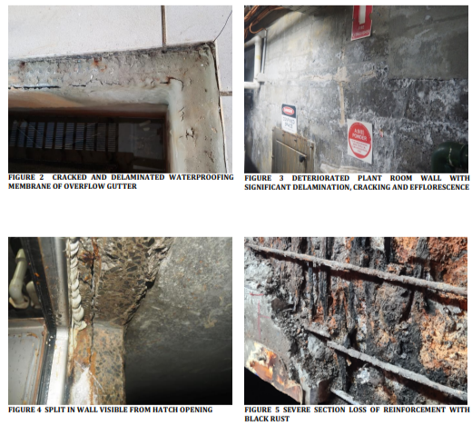
A reinforced concrete wall of a seawater swimming pool was found to have significant deterioration due to steel reinforcement corrosion. The wall in question is part of the plant room servicing the pool and faces the pool overflow gutter and backwash tank on the opposite side, as shown in Figure 1. The wall is 150mm thick with a single matt of steel reinforcement with an average cover of 60mm. The plant room is subject to elevated humidity and temperature due to the plant equipment circulating heated water to the pool. A waterproofing membrane had been installed on the overflow gutter wall; however, was found to be delaminated and cracked at multiple locations, as seen in Figure 2. This resulted in salt-contaminated water entering the concrete wall, exposing the reinforcement to high concentrations of chlorides and moisture. These chlorides originated from both natural salts found in seawater and from sodium hypochlorite used as a water disinfectant.

The configuration with the aerated plant room conditions formed a highly aggressive corrosion environment for the embedded steel reinforcement. The wall experienced significant cracking as shown in Figure 3, and one section was visibly bowing out due to a split along the plane of reinforcement, which was observable from the hatch opening as seen in Figure 4. Efflorescence was observed along the length of the wall especially around cracks, indicating moisture migration from the wall interior. A breakout of a section of the wall revealed a varied degree of steel corrosion, with some areas displaying 100% section loss and presence of black rust, as shown in Figure 5. Further breakout revealed multiple pockets of damp concrete where black rust was mainly observed. The inner vertical bars exhibited the most significant section loss, whereas the outer horizontal bars remained relatively intact for the most part.

Black Rust In Concrete
Corrosion of steel in concrete can result in a number of different corrosion products having different chemical compositions. One of the most common forms of rust observed in concrete is red rust or haematite (Fe2O3) which forms under high oxygen availability, and is expansive, generally leading to concrete cracking and staining. A less common form is black rust or magnetite which forms under low oxygen availability, typically in damp environments such as reinforced concrete soil retaining walls, or concrete structures situated near the water line. Formation of black rust is an aggressive form of corrosion and can be difficult to detect as minimal volume expansion occurs. As a result, significant reinforcement section losses can occur and may go unnoticed, making it a risky form of structural deterioration. (3)
The formation of black rust requires 3 conditions to be present (4):
- Availability of O2 at the cathode
- O2 depleted environment at the anode
- Low resistivity concrete to allow free flow of current between anodic and cathodic sites
Figure 6 shows a schematic illustration of how differential saturation and oxygen concentration can result in black rust formation in the case study described. The extent of section loss on the inner bars in contrast to the outer bars can be explained by a higher level of saturation and lower O2 availability at the inner bars (which become anodes), and, in contrast, a lower level of saturation and greater O2 availability at the outer bars (which can act as the cathode). The presence of moisture and mobile ions such as chlorides can provide a highly conductive path for ionic current to flow from the inner areas to outer areas resulting in black rust formation on the inner bars. Some parts of the outer bars also showed regular red rust corrosion.

Repair Of Wall
Infracorr Consulting were appointed as the design engineers for the repair and rehabilitation of the wall which included reinstatement of the waterproofing membrane (overflow gutter), concrete repair of the wall and installation of an ICCP system. The pool water was removed to enable the repair process including installation of gutter waterproofing and mitigate risk of failure to concrete repairs.
A partial depth breakout of the wall was specified to allow replacement of corroded steel with more than 10% section loss and the repair of deteriorated concrete. Over half the steel required replacement or supplementation. New bars were appended to existing bars in acceptable condition and new starter bars were epoxy grouted into the wall to replace the original starter bars which were severely deteriorated. The reinforcement matt following repair is shown in Figure 7, with electrical continuity fully restored. Negative connections were made to the steel reinforcement and references positioned prior to reinstating the concrete by wet spray shotcrete.
Following structural analysis of the wall, two reinforced concrete columns were incorporated to provide additional support. The old waterproofing membrane from the gutter was removed and replaced with a new polyurethane membrane system.

ICCP System
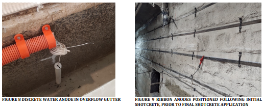
The design of the ICCP system was implemented using a dual approach, combining a concrete system with ribbon anodes and a water system utilizing discrete anodes placed in the overflow gutter as shown in Figure 8, which also provided protection to the pool walls. The ribbon anodes for the concrete ICCP system were installed after the initial layer of shotcrete was applied, as seen in Figure 9. Once in position along with titanium distributor bars, the final layers of shotcrete were applied to build the wall up to the final thickness.
The ICCP design was based on a long-term current density of 20mA/m2 steel, and in accordance with the “FHWA limit” of 110mA/m2 of anode surface area, as provided in the manufacturer’s data sheet for Elgard MMO ribbon mesh and consistent with AS2832.5. The data sheet also stated a limit for short-term anode current density of 220mA/m2 (which corresponded to 40mA/m2 steel in this design). The design adopted used 19mm wide Elgard 150 ribbon anodes at a spacing of ~200mm. The ICCP system was divided into 6 zones; upper and lower zones of the concrete wall (Zones 1 and 2 respectively) and the remaining 4 zones for each of the four anodes of the water CP system, which correspond to Zones 5-8 (Zones 3 and 4 are unused channels in the system). A remotely controllable transformer rectifier unit with datalogging capabilities was installed for ease of testing and monitoring.

Performance Assessments
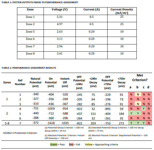
During commissioning, underperformance was noted for the concrete CP system and therefore the current was marginally increased above the design current density of 20mA/m2. Following initial adjustments, the output voltage and current for each zone recorded prior to performance assessment are summarised in Table 1. The system was turned off for 72 hours and the performance was assessed against the criteria stated in AS2832.5, the results of which are summarised in Table 2. All potentials are with respect to silver-silver chloride 0.5M KCl reference electrodes and all zones were operating in constant current mode.

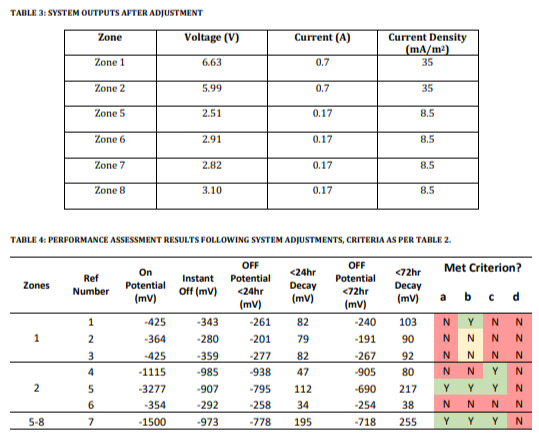
Based on the results of the performance assessment, the currents of the concrete CP Zones 1 and 2 were increased while those of the water anode Zones 5-8 were reduced, as detailed in Table 3 below. The system was energised for approximately 1 month at the new settings before a second performance assessment was conducted, the results of which are summarised in Table 4.

Discussion
Despite increasing the current for the concrete wall Zones 1 and 2 by 40%, which corresponded to a relatively high current density of 35mA/m2 steel, the results of the performance assessment indicated only marginal improvements. In the upper wall Zone 1, Reference 1 changed from failing to meet any criteria to passing criterion b, the extended depolarization criterion. References 2 and 3 almost passed criterion b but fell short by a few millivolts.
In the lower wall Zone 2, reference 4 met the absolute potential criterion c and reference 5 met criteria a, b & c. Reference 6, with a low depolarization of only 38mV, did not meet any criteria and is being further investigated. The water CP system, Zones 5-8, was noted to perform adequately even after reduction of the output current.
The observations for the concrete CP system performance, Zone 1 & 2, assessments indicate that the current applied is not sufficient to fully meet the AS2832.5 criteria. However, it should be noted that the wall has a very high moisture content and accordingly the rate of depolarization is very slow. This may also explain why the natural potentials were found to be more negative than expected following concrete repairs. A moisture content survey was performed on the wall surface which revealed an average moisture content of 1.4% at the upper region of the wall and 2.9% at the bottom. Future depolarization testing will include extending the depolarization period beyond 72 hours, and it is expected that the reinforcement measured by several Zone 1 references will then reach 100mV depolarisation.
While future monitoring and adjustments will fine tune the current levels for the concrete zones, it is clear that the system will need to operate at a steel current density around 35 – 40 mA/m2 steel to maintain sufficient protection levels. This means that the long-term operating current of the system is above the design current density of 20mA/m2, which may increase the risk of accelerated acid generation and acid attack around the anodes.
Conclusions
The high chloride and very high moisture conditions of this pool wall have led to high levels of reinforcement corrosion and black rust generation resulting in significant reinforcement section loss, spalling and delamination of the concrete.
The impressed current cathodic protection system was designed for a long-term current density of 20mA/m2 steel (a short-term current density of 40mA/m2) and has been operating at a level of ~35mA/m2 and not fully achieving the criteria set out in AS2832.5. This may be because of slow depolarisation in saturated concrete, but this is still being investigated.
In similar conditions of high chloride, and in moist conditions that have caused or could lead to black rust formation, increased design CP current densities should be considered, possibly up to 50mA/m2 steel.
Acknowledgments
The authors thank Kate Nairn from Infracorr Consulting for her helpful insight and discussion.
References
- AS2832.5 – Cathodic protection of metals: steel in concrete structures: Standards Australia; 2008 (R2018).
- Chess P, Broomfield JP. Cathodic Protection of Steel in Concrete and Masonry. Second Edition ed.; 2014.
- Bennison P. Repair and protection of reinforced concrete bridges. In Cope RJ, editor. Concrete bridge engineering – performance and advances.: CRC Press; 1987.
- O’Donovan R, et al. Anaerobic Corrosion of Reinforcement. Key Engineering Materials. 2013; 569-570.
Author Details
Ian Godson is the Managing Director and Principal Engineer of Infracorr Consulting. Ian has over 35 years’ experience in all aspects of remedial engineering including condition assessment, remedial design and cathodic protection design and installation. Ian has led Infracorr in major CP projects including Port of Melbourne’s Swanson Dock West and Webb Dock East 4&5, NSW Ports Brotherson Dock and Bulk Liquid Berth, and BHP Hay Point Berth 2 Caissons. Ian is currently the Chair of the ACA Foundation and past president of the Concrete Institute (CIA Vic) and the formation President of ACRA (Australasian Concrete Repair Association).
Shamir Bhuiyan is an Engineer for Infracorr Consulting with a Civil and Structural Engineering background. Since joining Infracorr in 2021, Shamir has been involved in a variety of remedial projects which include design, investigation and condition assessment works. Prior to his role at Infracorr, Shamir worked in RMIT University’s Civil Engineering laboratories and has assisted numerous research projects. Shamir has a keen interest in Cathodic Protection systems and is currently pursuing a PhD in this field.
Nathan is a Materials Technologist at Infracorr Consulting Pty Ltd with a Bachelors of Science (Hons), Majoring in both Chemistry and Materials Science. Joining Infracorr in 2017, Nathan has worked a broad range of structures in including bridges, mining assets, commercial import and export wharfs, heritage structures and buildings; delivering durability investigations, project management, design, and remediation works including various corrosion and cathodic protection systems. Prior to working at Infracorr, Nathan spent time working and conducting research in multi polymer additive manufacturing (3D Printing) at Monash University and nanomaterial research at CSIRO’s Manufacturing Flagship.