Authors: Turnbull, R. G. Metcalfe
This paper was presented at the Corrosion & Prevention 2023.
ABSTRACT
Two (2) first stage impellers removed from high flow pumps operating in a waste management industrial dam that exhibited reduced pumping capacity, were investigated to determine the likely cause of the observed decrease in efficiency.
Loss of pump efficiency was the result of a combination of cavitation and corrosion in which blistering of the coating through osmotic pressure may have played a part. Corrosion was present on all exposed surfaces, as well as beneath the protective coating at locations of impaired integrity.
The locations of loss of 100% of impeller vane wall thickness were consistent with the positions most susceptible to cavitation, suggesting cavitation as the more dominant contributor to the failure. Corrosion occurred when the pumps were submerged and sitting idle as well as during periods of operation.
Keywords: pump impeller, industrial dam water, corrosion, cavitation
Introduction
An investigation was undertaken on two first stage impellers removed from two of a total of three 3-stage high flow pumps. It was understood that the pump performance had decreased over time and had reached a stage where they could no longer operate within their designed operating curve. The pumps operated within a waste management industrial dam. It was understood that the impellers had been cast from a high nickel corrosion resistant ductile cast iron specified as ASTM A439 Grade D2.
All three pumps operated during rain events when it is necessary to lower the dam level. Outside flood or rain events, one or two pumps operated only when the water level required lowering. It was understood that the wastewater management system was designed to operate with all three pumps running when required. When only one pump operated, it was understood that the decrease in the net positive suction head could reduce to a theoretical level that would result in cavitation.
The pumps were all commissioned at the same time, approximately eight years prior to removal from service. They had operated only when necessary, suggesting that they were stationary in the water for a considerable proportion of their service life. It was understood one of the pumps was used more frequently for lowering the dam level, although the task was typically shared between the two pumps provided for investigation. The pump that had been
used the least, had remained in service and continued to operate within expected parameters, i.e., there was no apparent loss of capacity.
A waste dam water analysis was not available at the time of writing, but it was understood that the dam water contained ultrafine coal particles that can increase in concentration during flood events.
Investigation
Visual Inspection
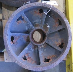
The first stage impellers labelled HFP1 and HFP2 by the client are shown as received in Figure 1. The impellers had a maximum outside diameter of approximately 340mm, height 180mm and bore diameter 80mm. The impellers had seven vanes each with a trailing-edge thickness of approximately 10mm. Both impellers had a protective coating that had been damaged or partially lost. No information was available regarding the type or nature of the coating.
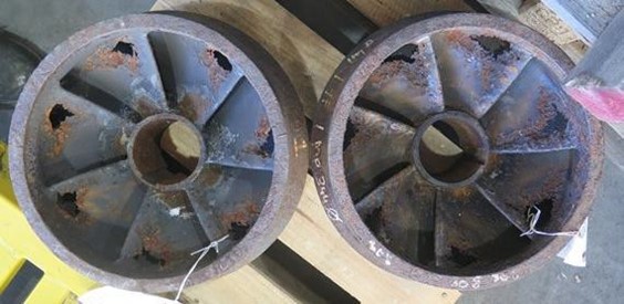 |
| FIGURE 1. IMPELLERS AS RECEIVED, HFP1 (RIGHT) AND HFP2 (LEFT) |
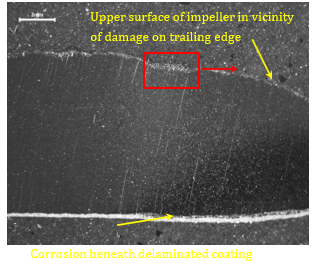
Both impellers exhibited complete loss of wall thickness, with a pitted appearance, at the outer region of each vane, adjacent to the trailing edge, as well as general corrosion on the surfaces that had lost the protective coating (Figure 2). Complete loss of wall thickness at the same position on the trailing edge of each vane is typically considered an indication of cavitation.
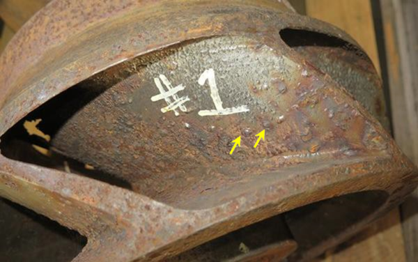
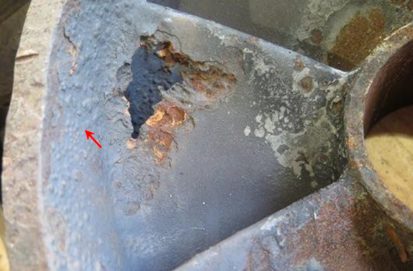
The trailing edge of each vane on HFP1 exhibited loss of the protective coating and general corrosion of the exposed surface surrounding the pitted region (Figure 3). Discrete blisters were present on the coated surface, more noticeable closer to the pitted region.
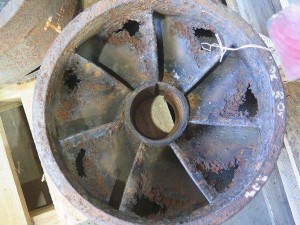 | 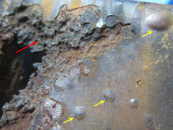 |
| FIGURE 2. HFP1 EXHIBITING COMPLETE LOSS OF WALL THICKNESS AT SAME POSITION AT THE OUTLET SIDE OF EACH VANE | FIGURE 3. HFP1 – DAMAGE EXHIBITED A PITTED APPEARANCE IN THE MORE SIGNIFICANT DAMAGE (RED ARROW), DISCRETE BLISTERS (YELLOW ARROWS) AND GENERAL CORROSION WHERE THE COATING HAD BEEN LOST |
The pitted region exhibited an oxide (corrosion) coating (Figure 4). Some of the pits exhibited a cave-like appearance. High power magnification of the pitted surface indicated an oxide coating (Figure 5). There was no exposed fresh metal surface that would provide conclusive evidence of mechanical damage consistent with cavitation.
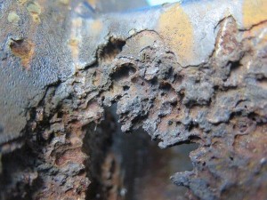 | 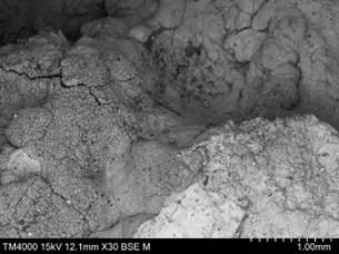 |
| FIGURE 4. HFP1 PITTING TYPE DAMAGE ON TRAILING EDGE OF VANE | FIGURE 5. HFP1 – PITTED REGION OF SURFACE WITH OXIDE COATING. SEM PHOTOMICROGRAPH. MAGNIFICATION X30 |
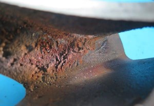
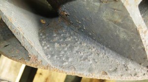
The underside of the vanes exhibited minor damage, blisters and localised loss of the protective coating (Figure 6). The inside surface of the outside diameter exhibited erosion or cavitation erosion type damage adjacent to the 100% loss of vane wall thickness (Figure 7). This region of damage was also coated in corrosion product.
HFP2 impeller exhibited very similar but less severe pitting type damage to that observed on HFP1, indicating a common damage mechanism across both pumps (Figure 8 and Figure 9). HFP2 exhibited more severe blistering of the coating, compared to HFP1 (Figure 10).
 |  |
| FIGURE 6. HFP1 UNDERSIDE OF A VANE EXHIBITING MINOR DAMAGE, BLISTERS (YELLOW ARROWS) AND LOCALISED LOSS OF THE COATING | FIGURE 7. HFP1 CENTRAL BORE – EROSION TYPE DAMAGE TO BORE WALL ADJACENT TO 100% LOSS OF VANE WALL |
 | 
|
| FIGURE 8. HFP2 IMPELLER EXHIBITING VERY SIMILAR DAMAGE, BUT LESS SEVERE | FIGURE 9. DAMAGE ON HFP2 VANE VERY SIMILAR TO HFP1. BLISTERING OF COATING ON SIDE WALL (RED ARROW) |
 | |
| FIGURE 10. HFP2 – MORE SEVERE BLISTERING ON SIDEWALL COMPARED TO HFP1 |
The underside of HFP2 exhibited wear of the inside edge of the end face, extending around approximately 50% of the circumference (Figure 11). The end face exhibited relatively large, but very shallow, pitting, that was not observed at the same position on HFP1.
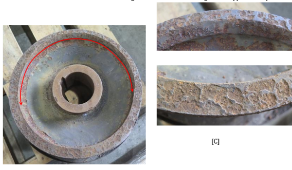
FIGURE 11. HFP2 – [A, B] WEAR ON INSIDE EDGE OF END FACE, [C] CORROSOIN ON END FACE
In general, HFP1 exhibited more severe pitting damage resulting in 100% loss of wall thickness, while HFP2 exhibited more severe corrosion damage. This suggests that HFP1 operated at a low net positive suction head more than HFP2 and HFP2 was stationary more than HFP1.
Chemical Analysis
Impeller
The impeller had been cast from a nickel chromium austenitic ductile cast iron consistent with ASTM A439 Grade D2, although with higher than specified carbon content (Table 1).
TABLE 1. CHEMICAL ANALYSIS RESULTS – HFP1
| C | Mn | P | S | Si | Ni | Cr | Mo | Nb | Mg | Cu | |
| Pump | 5.48 | 0.87 | 0.028 | 0.023 | 2.35 | 21.80 | 1.96 | 0.01 | 0.014 | 0.139 | 0.04 |
| A439- D2* | 3.00 | 0.70- 1.25 | 0.08 | 1.50- 3.00 | 18.00- 22.00 | 1.75- 2.75 |
*Maximum unless otherwise stated
Corrosion Product
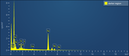
Analysis of the corrosion product within a pitted region of HFP1 indicated an iron-nickel oxide, consistent with oxidation of the impeller material (Table 2). Phosphorous, calcium and sulphur were also present and likely originated from the dam water.
Analysis of the underside of a blistered region on HFP2 provided results very similar to that of the corrosion product on the pitted surface of HFP1.
Chlorine, which is corrosive to most steel and irons, was not present at measurable concentrations at either location.
TABLE 2. CHEMICAL ANALYSIS RESULTS – CORROSION PRODUCT HFP1
|
Hardness Testing
Testing indicated an average hardness of 155HV (approximately 147HB) which was consistent with the range 139HB to 202HB stated for ASTM A439 Grade D2.
Metallography
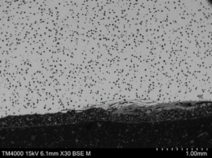
Two sections transverse to a vane, one that intersected a region of 100% loss of wall thickness and the other intersecting a blister on the trailing surface, were removed from HFP1 impeller and prepared for metallographic examination. It should be noted that the blistered coating was lost during sample preparation, leaving a relatively shallow pit on the surface.
The section that intersected a blister is shown in Figure 12. The blister was an indication of localised delamination of the protective coating and corrosion of the surface. At higher magnification it was apparent that the almost fully oxidised surface beneath the blister was beginning to separate (exfoliate) from the impeller vane surface, leaving a slightly deeper pit. Delamination or debonding of the coating on the underside of the vane was associated with corrosion of the vane surface.
 |  |
| Figure 12. HFP1 [A] Low power magnification of metallographic sample intersecting shallow pit at trailing edge of vane. Corrosion presents beneath delaminated coating on underside. [B] Shallow pit resulting from exfoliation of corroded region (Magnification X30) | |
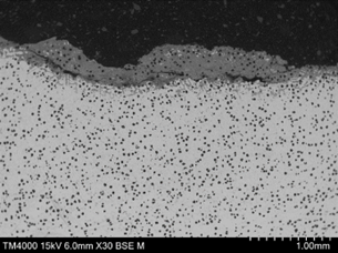
The underside surface exhibited corrosion and near-surface cracking that was parallel to the surface at locations where the coating had debonded (Figure 13). The impellor surface where the coating remained bonded was free of corrosion.
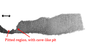
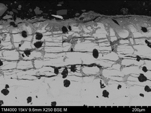
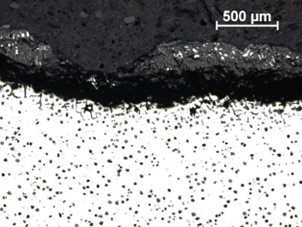
Low power magnification of the sample through a region of complete loss of wall thickness indicated pitting with
a wide, shallow profile, as well as a “cave-like” pit, similar to undercutting or sub-surface pitting (Figure 14).
 |
|
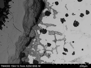
| FIGURE 13. HFP1 – CORROSION ON SURFACE WHERE COATING HAS DEBONDED (RIGHT), NO CORROSION WHERE COATING BOND HAS REMAINED (LEFT). SEM PHOTOMICROGRAPH. UNETCHED, MAGNIFICATION X30 | FIGURE 14. HFP1 – LOW POWER MAGNIFICATION OF METALLOGRAPHIC SECTION THROUGH PITTED REGION |
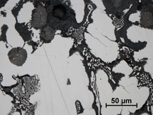
The impellor microstructure exhibited spheroidal graphite nodules and a chromium rich interdendritic eutectic within a nickel rich austenite matrix (Figure 15).
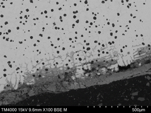
The side wall within the pitted region exhibited a relatively thick oxide coating with preferential corrosion surrounding the chromium rich eutectic phase (Figure 16). Cracking was present and was, mainly, aligned roughly parallel to the surface. The cracking appeared to originate at the corroded interface between the
chromium rich eutectic phase and the austenite matrix, but also passed through or around graphite nodules. The form of corrosion was very similar at the base of the pitted region although not as severe (Figure 17).
 |  |
| FIGURE 15. HFP1 – IMPELLER MICROSTRUCTURE EXHIBITING SPHEROIDAL GRAPHITE NODULES AND CR RICH INTERDENDRITIC EUTECTIC IN A NICKEL RICH AUSTENITE MATRIX. ETCHANT 2% NITAL + 5% PICRAL, MAGNIFICATION X500 | FIGURE 16. HFP1 – PITTED REGION SIDE WALL EXHIBITING OXIDE COATING (ON LEFT) AND PREFERENTIAL CORROSION AROUND CR RICH EUTECTIC PHASE. CRACKING PARALLEL TO SURFACE ALSO PRESENT. SEM PHOTOMICROGRAPH. UNETCHED, MAGNIFICATION X250 |
 |  |
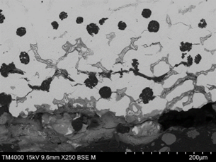
| FIGURE 17. HFP1 – BASE OF PITTED REGION EXHIBITING PREFERENTIAL CORROSION SURROUNDING CR RICH EUTECTIC BUT LESS CRACKING. ETCHANT 2% NITAL + 5% PICRAL, MAGNIFICATION X200 | FIGURE 18. HFP1 – UPPER SURFACE OF VANE ADJACENT TO PITTED REGION EXHIBITING PREFERENTIAL CORROSION SURROUNDING CR RICH EUTECTIC AND EXFOLIATION TYPE CRACKING ASSOCIATED WITH LATERAL CRACKS. SEM PHOTOMICROGRAPH. UNETCHED, MAGNIFICATION X250 |
The upper surface of the vane, adjacent to the pitted region and within an area that had lost the protective coating exhibited the same form of corrosion, however the depth of corrosion and density of cracking parallel to the surface was greater than that within the pitted region (Figure 18). The cracking at this location was both parallel (lateral) and perpendicular (transverse) to the surface. Lateral cracking had likely initiated at graphite nodules and was free of corrosion at depth, suggesting that the cracks formed first, with moisture ingress following. Transverse cracking appeared to link the lateral cracks and had propagated both along the austenite/Cr rich eutectic phase boundaries and through the austenite matrix. The underside surface of the vane, within a region that had lost the protective coating, exhibited the same form of damage but to a greater depth in some areas (Figure 19 and Figure 20). The corroded regions exhibited a dendritic pattern at some locations, with cracking following the dendrite arms, where they were parallel to the surface. Corrosion beneath a blister was of the same nature (Figure 21).
 |  |
| FIGURE 19. HFP1 – UNDERSIDE OF VANE EXHIBITING PREFERENTIAL CORROSION OF INTERDENDRITIC REGION LEADING TO SPALLING/CRACKING. SEM PHOTOMICROGRAPH. UNETCHED, MAGNIFICATION X100 | FIGURE 20. HFP1 – UNDERSIDE OF VANE EXHIBITING PREFERENTIAL CORROSION SURROUNDING CR RICH EUTECTIC AND EXFOLIATION TYPE CRACKING. SEM PHOTOMICROGRAPH. UNETCHED, MAGNIFICATION X250 |
 [A] | 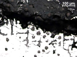 [B] |
| FIGURE 21. HFP1 – [A, B] CORROSION BENEATH BLISTER SIMILAR TO THAT OBSERVED ELSEWHERE ON THE SURFACE, LATERAL TRANSGRANULAR CRACKING ROUGHLY PARALLEL TO SURFACE. UNETCHED, MAGNIFICATION [A] X50, [B] X200 | |
 | |
| FIGURE 22. HFP1 – CORROSION OF REGION SURROUNDING CR RICH EUTECTIC, MINOR ATTACK SURROUNDING GRAPHITE NODULES, CRACKING PROPAGATING FROM CORRODED REGION. UNETCHED, MAGNIFICATIN X500 | |
At higher power magnification it was apparent that corrosion had occurred preferentially at the boundary between the interdendritic chromium rich eutectic and the austenite phase (Figure 22). Localised corrosive attack had followed cracking, both transverse and lateral. Corrosion product along cracking, grain or phase boundaries will exert pressure resulting in a lifting or leafing effect, known as exfoliation. Exfoliation is a form of intergranular corrosion that is more common in aluminium alloys, but can be found in ferrous alloys, particularly when submerged in water.
Elemental mapping of a corroded region on a metallographic sample indicated preferential corrosion immediately surrounding the chromium rich eutectic phase and some concentration of silicon at the impellor surface (Figure 23).
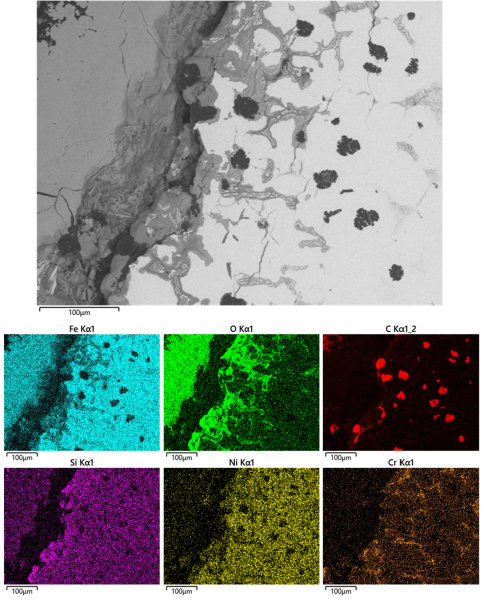 |
| FIGURE 23. EDS ELEMENTAL MAPPING OF CORRODED AREA |
Discussion
The reduced capacity of the pumps was attributed to localised loss of 100% of wall thickness at the trailing edge of each impeller vane. Damage of this nature is typically attributed to cavitation. However, corrosion was present on all exposed surfaces, including within the pitted region adjacent to 100% loss of wall thickness, although to a lesser extent. Given the general presence of corrosion, but localised loss of wall thickness, it was considered that cavitation had been present. The consistent location of damage to both impellers at what would be the high pressure side of the impeller vanes adjacent to the volute casing is consistent with a mechanism of cavitation-erosion [1], [2], [3].
Cavitation occurs when vapour (bubbles) forms within the liquid at a low pressure. As the liquid passes from the low-pressure suction side to the high-pressure delivery side of the impeller, the bubbles implode, creating a compressive stress shockwave, that if close enough will impact the impeller surface causing mechanical damage and micro-fracture leading to the loss of surface material [1], [2], [3].
Because the deterioration of the surface of a material due to cavitation-erosion is a mechanical process its resistance to erosion is related to its mechanical properties such as tensile strength, hardness, fatigue strength and fracture toughness [2], [4], [5]. In this respect the presence of a graphite phase in the matrix has a significant effect with the cavitation erosion of cast iron being significantly higher than steel of similar hardness due to the stress concentration effect of the graphite [6].
The degradation of ductile iron due to cavitation has been found to initiate with the fragmentation of the graphite nodules and separation at the nodule/matrix interface leading to the formation of micro-cavities. With continued exposure, micro-cavities also begin to form in the matrix unrelated to the former nodule positions. The micro- cavities continue to grow in size, acting as stress concentrations for cracking of the matrix leading to cracking of the matrix through processes of ductile tearing from the base of the cavities into the matrix or laterally by brittle fracture [4], [7], [8].
In materials operating in a corrosive environment, the lack of corrosion product on the surface is often used as verification that they have been exposed to cavitation erosion [1]. In the present instance this cannot be definitive due to the intermittent operation of the pump. Corrosion was present on all exposed surfaces, both within the cavitation damage and exposed surfaces, as well as along cracking. The lateral subsurface cracking within corroded regions was likely the result of brittle fracture due to cavitation stresses and volume increase of corrosion product.
The shallower depth of corrosion and reduced density of lateral cracking within the pitted/cavitation damage was likely the result of loss of surface material due to the cavitation erosion mechanism. Corrosion would become active during periods when the pumps were idle and submerged in the dam.
Blistering and delamination of the protective coating was considered to most likely be a result of osmotic pressure in which water is absorbed through the coating to the metal substrate. With continued diffusion through the coating a pressure build-up occurs leading to coating delamination and blister growth through coating deformation. While the coating remains intact, substrate corrosion will be restrained, however if the coating ruptures corrosion of the metal surface can occur more rapidly. [9], [10], [11]. Within the region exhibiting cavitation, it is possible that blister formation had preceded cavitation damage and if so, their presence would be expected to reduce the resilience of the coating to cavitation, leading to destruction of the coating and exposure of the metal substrate.
The impellers had been cast from an austenitic ductile iron consistent with the specified Ni-Resist ASTM A439 Grade D2.
Ni-Resist alloys typically corrode in a uniform (general) manner, at relatively low rates. The corrosion product tends to form a dense, adherent coating that suppresses further corrosion. However, cavitation erosion would have resulted in fracture of the protective oxide coating leaving fresh, unprotected metal exposed to the corrosive medium. Lateral cracking, and subsequent transverse cracking, resulting from cavitation had provided pathways for corrosion, leading to exfoliation.
Analysis of the corrosion product did not identify a specific corrosive species, suggesting the pH of the wastewater may have contributed.
Conclusions
Loss of pump functionality caused by 100% loss of wall thickness adjacent to the trailing edge of the impeller vanes was the result of a combination of cavitation erosion and corrosion in which blistering of the coating through osmotic pressure may have played a part. Lateral cracking that had formed between graphite nodules as a result of cavitation and subsequent transverse cracking had provided pathways for corrosion leading to exfoliation type corrosion.
Accelerated loss of wall thickness had occurred in localised areas, however the severity of corrosion at these locations was less than elsewhere. It was considered that cavitation erosion was present. Cavitation would have resulted in loss of surface material, giving the appearance of reduced corrosion attack, but increased rate in loss of material.
Acknowledgments
The authors would like to thank Bureau Veritas AIRS for granting permission to publish this paper.
References
| [1] | M. Binima, A. Muhirwa and E. Bisengimana, “Cavitation effects in centrifugal pumps – A review,” International Journal of Engfineering Research and Applications, vol. 6, no. 5, pp. 52-63, 2016. |
| [2] | D. E. Zakrzewska and A. K. Krella, “Cavitation erosion resistance influence of material properties,” Advances in Materials Science, vol. 19, no. 4, pp. 18-34, 2019. |
| [3] | N. Pokharel, A. Ghimire, B. Thapa and B. S. Thapa, “Wear in centrigugal pumps with causes, effects and remedies: A review,” IOP Conference Series: earth and Enfironmental Science, vol. 1037, no. 1, p. 012042, 2022. |
| [4] | O. Eric Cekic, M. Dojcinovic, D. Rajnovic, L. Sidjanin and S. Balos, “Microstructure and cavitation behaviour of alloyed austempered ductile irons,” Internation Journal of Cast Metals Research, vol. 31, no. 5, pp. 279-287, 2018. |
| [5] | A. K. Krella, “Degradation and protection of materials from cavitation erosion: A review,” Materials, vol. 16, no. 5, p. 2058, 2023. |
| [6] | M. Dojčinović, O. Erić, D. Rajnović, L. Šiđanin and S. Baloš, “The morphology of ductile cast iron surface damaged by cavitation,” Metallurgical and Materials Engineering, vol. 18, no. 3, pp. 165-176, 2012. |
| [7] | A. H. Al-Hashem, V. K. Gouda, A. M. Adbullah and W. T. Riad, “Cavitation-corrosion behaviour of nodular cast iron in aqueous environments,” Journal of King Saud University Engineering Sciences, vol. 8, pp. 1-19, 1996. |
| [8] | M. Freitas de Abreu, Cavitation erosion mechanisms in cast irons, Stockholm: KTH Royal Institute of Technology, 2021. |
| [9] | C. H. Hare, “Blistering of Paint Films on Metal, Part 1: Osmotic Blistering,” Journal of Protective Coatings and Linings, vol. 15, pp. 45-63, 1998. |
| [10] | R. P. Berkelaar, P. Bampoulis, E. Dietrich, H. P. Jansen, X. Zhang, E. S. Kooij, D. Lohse and H. J. Zandvliet, “Water- induced blister formation in a thin film polymer,” Langmuir, vol. 31, no. 3, pp. 1017-1025, 2015. |
| [11] | S. Effendy, T. Zhou, H. Eichman, M. Petr and M. Z. Bazant, “Blistering failure of elastic coatings with applications to corrosion resistance,” Soft Matter, vol. 17, no. 41, pp. 9480-9498, 2021. |
Author Details
Judy Turnbull
She is a Senior Consultant Metallurgist with Bureau Veritas, undertaking component failure investigations. She has held this role since 2013. Judy has more than 30 years’ experience in the engineering field, having worked in heavy engineering, hard rock mining, concrete, oil & gas and pipeline inspection as well as information technology.
Judy holds a Bachelor of Metallurgy as well as a Diploma in Software Development and is a Fellow of The Institute of Materials, Minerals and Mining (UK)
Roger Metcalfe
He is a Principal Consultants Metallurgist, undertaking component failure investigations with Bureau Veritas. He has more than 40years experience in heavy industry, including more than 30years failure analysis, in addition to experience in quality control and project management, within an iron and steel foundry, and process development and improvement within a steel making and primary rolling mill environment.
Roger holds Bachelor degrees in Metallurgy and Arts along with a Master’s
degree in Educational Studies.