Author: Charles Perrie
This paper was presented at Corrosion & Prevention 2023.
ABSTRACT
Corrosion Under Insulation (CUI) can prove a difficult corrosion mechanism to detect. In many cases the piping or vessel insulation can mask this corrosion problem until it is “too late” resulting in a pipe or vessel failure. CUI is a real threat to the integrity and reliability of many industries processing plants and facilities. CUI can result in failures in parts of the plant that may not normally be considered as part of inspection regimes, thus increasing the risk for potential failures. Failures from CUI are often the result of localised corrosion and not general wastage over a large area, which increases the difficulty to develop a cost-effective inspection program, often needing to cover many hundreds of thousands of kilometres on insulated piping across a wide range of industries. Failures from CUI can be catastrophic or have a significant impact on safety or have serious economic consequences on an asset. Economic consequences are mainly due to lengthy downtime and repairs following an unexpected failure. Removal of insulation from vessels, piping and other assets for a visual inspection, is very expensive and time consuming, so a screening inspection solution is required. A global leader in the Oil and Gas industry quoted several years ago that “CUI issues were the cause of 80% of all unplanned shutdowns at our plants globally”. Whilst there are a number of CUI detection methods currently being used to inspect for CUI, unfortunately there is no “silver bullet” providing complete detection reliability. With this in mind, it is important to develop an effective screening strategy to try and determine the extent of any CUI, followed by a robust and effective quantitative assessment. All of this should be performed using industry “best practice” inspection technology. Any strategy should be structured, robust and appropriate for inspecting pipework, vessels, towers and other insulated components to detect CUI. Adopting this approach is far better than doing nothing.
Keywords: Inspection, Methods, Non-Destructive Testing (NDT) CUI, Piping, Vessels, Tanks
INTRODUCTION
As the world advances and embraces an environmentally friendly era and struggles to cope with the volatile financial markets, it will become more and more important that structural integrity management strategies remain robust and relevant so that existing infrastructure can be safely and reliably maintained over the next 10 to 20 years and beyond. This will only be achieved through cost effective and financially viable asset management processes and strategies. However, without reliable supporting inspection technology this will not be achieved. Inspection underpins all integrity management strategies and processes, but only appropriate and reliable inspection technology will make this happen.
DISCUSSION
For plant operators to continue to operate safe and reliable plant and equipment, as well as meet operation objectives like shorter inspection and maintenance shutdowns, longer intervals between shutdowns, and to minimise unplanned shutdowns, they will require more accurate and quantitative inspection data. This means that non-destructive testing (NDT) and inspection in general must meet this demand. There is already a big demand for this to occur, and it is important that industry is prepared to meet this challenge both with sophisticated inspection techniques as well as skilled and trained operators.
Plant owner/operators need to change their approach to inspection, from the “tick the box” attitude to one of engineering assessment and planning. The inspection industry can broadly be broken into two sectors: namely, onshore assets and offshore assets. Each of these environments demands a different approach, as they both have different safety, environment and risk profiles. This paper will deal mainly with onshore assets
Engineering assessment or engineering led decisions will drive future inspection requirements. This means that engineers will identify what damage mechanism is likely to occur, where it is likely to occur and from that, inspection strategies and planning will be developed. If all this can be completed while the plant or component is still operating, i.e. outside of a shutdown, then this will be an advantage.
Statutory inspection codes and standards like AS/NZS3788 will need to be met by operators and owners but more responsibility, self-regulation and goal-based integrity, will be the norm. This is already happening throughout the world and is becoming more prevalent here in Australia. The change will happen and will be enormous. Financial performance drivers, cost cutting and limited availability to capital to replace ageing assets will make this change inevitable. Forward thinking and a greater knowledge of integrity deliverables is essential.
This means that inspection technology, equipment manufactures, and inspection service providers will also have to embrace this approach and gear up for it. Technologies such as RBI (Risk Based Inspection), NII (Non-Intrusive Inspection) are now recognised by codes and standards and will continue to be used and drive plant integrity management. Inspection techniques will need to be there in support of this growing demand.
A significant integrity issue facing all plant owners and plant operators is how to manage and stay on top of CUI. This damage mechanism affects all process plants and although the causes are generally understood, where and how to inspect for CUI is a big problem. Unfortunately, where CUI occurs is not easy to predict and therefore any inspection strategy must include a “seek or search” thinking and the use of screening inspection techniques can play a valuable part in doing this.
By definition, CUI can be defined as corrosion of piping, pressure vessels and structural components resulting from water trapped under insulation or fireproofing.
CUI can cause failures in areas that are not normally of a primary concern to an inspection program, and, in addition, CUI is particularly aggressive where operating temperatures cause frequent condensation and re-evaporation of atmospheric moisture. Insulated piping is particularly difficult to inspect due to the vast lengths of piping in a plant as well as the pipework being typically challenging to access. Failures of this piping are often the result of localised corrosion and not general wastage. Because of this, it is difficult to develop a cost-effective inspection program 3covering the ‘what and where’ to inspect. Unfortunately, often failures from CUI are catastrophic in nature, with high consequence.
There are some guidelines outlined in the API RP 574 originally published in 1998, and updated in 2016, that can be used as a starting point when developing an inspection strategy. In addition, AS/NZ 3788 Appendix I also outlines what must be considered when managing piping at high pressure and temperature. Some considerations include the following:• Areas exposed to mist overspray from cooling water towers.
- Areas exposed to steam vents.
- Areas exposed to deluge systems.
- Areas subject to process spills, ingress of moisture or acid vapours.
- Carbon steel piping systems, including those insulated for personnel protection, operating between -5° C and 120° C (although CUI can occur across a wider temperature range than this).
- Dead legs and attachments that protrude from insulated piping and operate at a temperature different from the active line.
- Vibrating piping systems that have a tendency to inflict damage to insulation jacketing thus providing a path for water ingress.
- Steam traced piping systems that may experience tracing leaks, especially at the tubing fittings beneath the insulation.
- Piping systems with deteriorated coatings and/or visual damage to lagging.
- Cracked fireproofing.
- Brown/orange staining.
- Modifications to piping without repairing the insulation.
This list is not exhaustive and currently there is no one inspection method that can achieve a full and final inspection and deliver a definitive outcome for the above potential areas of concern. Some of the available inspection methods include the following, but all have capability as well as limitation:
- Neutron Backscatter.
- Infrared Thermography.
- Guided Wave Testing (GWT).
- Real Time/Conventional (RT), OpenVision
- Flash Radiography.
- Bracelet Probe – Electromagnetic.
- EMAT (electro-magnetic acoustic transducers).
- Pulsed Eddy Current.
- Visual – Insulation/fireproofing removal.

It has been found that on-going and regular inspection surveys using a combination of inspection methods can reduce the risk of CUI going unnoticed and can minimise the potential for catastrophic or unplanned outages and failures. However, any inspection method used should have the following benefits:
- High or reasonable probability of detection (POD) – probably the most important aspect of any inspection method used, not only for CUI but for inspection in general.
- Ease of use and should be cost effective (the aim is to create an inspection strategy that will cost less than insulation removal and replacement).
- Should be able to scan through insulation, coatings, etc. (this is a huge benefit as it limits the costly removal of insulation).
- Access requirements need to be considered – a considerable amount of piping is located in pipe racks or at elevated levels.
- Up-front engineering review to identify likely locations – this can definitely form the base starting point for the inspection strategy.
- Visual assessment/verification process to support the above.
In the UK trials were held under the control of HOIS (a widely respected joint industry project and forum, with 41 members comprising oil and gas producers, NDT service companies, equipment vendors and a regulatory authority) to determine the effectiveness of different inspection techniques for the inspection of CUI, Anon (2017). HOIS is a joint industry project (JIP) which has been running for more than 40 years. The project is managed by ESR Technology in the UK https://www.esrtechnology.com/index.php/centres-of-excellence/hois
Some very good lessons were learnt from this trial, but what was evident was that in many cases, when the methods were used in real life field applications, they did not perform exactly as the manufacturer had indicated; so there is, in some cases, a disconnect between the “glossy brochure” and the reality on the ground. It is such trials that help users of this technology sort fact from fiction.
HOIS has a vision and that is to improve the effectiveness of in-service inspection for the oil and gas industry, but inspection methods cut across all industries. The HOIS vision includes the following:
- More reliable in-service inspection – better detection of in-service degradation.
- More accurate measurements of remaining wall thickness.
- Providing asset owners with improved information on asset condition.
- Reducing leaks and near misses.
Although this was not a definitive guide to effective inspection techniques, it does outline and highlight some effective methods and some not-so-effective methods. By using a range of inspection methods in the field, each technique can be evaluated on its merit. Some of the available inspection techniques are considered below.
Inspection techniques
Most inspection techniques that are applicable to the detection of CUI can be considered advanced inspection methods and should be deployed by trained and experienced advanced inspection technicians. This paper outlines some of the effective techniques available across Australia, for the detection of CUI. They are discussed in no particular order.
Neutron Backscatter
Neutron backscatter operates by emitting neutrons into the equipment being tested. The higher energy neutrons are moderated by collision with hydrogen atoms in trapped moisture within the insulation/fireproofing. These moderated neutrons are then counted. Wet insulation will produce a higher count per unit of time than dry insulation. So, while this technique (Figure 2) does not indicate the presence of active CUI, it does indicate the presence of moisture, and therefore is a good indicator that CUI may be present. A limitation of this method is the likelihood of obtaining a “false call” due to the possible presence of moisture in adjoining pipework not under investigation. This method is not in regular use because of these potential false calls.
Thermographic scanning – Infrared Thermography
The thermography technique uses infrared sensitive cameras to monitor the surface temperature of sections of piping, vessel, etc. This can detect thermal change in the insulation, as well as the presence of moisture ingress in the insulation. For this to occur, wet areas of the insulation will appear hotter than the surrounding area when scanning sections, or warmer than ambient process piping/vessels etc. Although this method does not generally detect CUI, wet insulation can be an indication that CUI is present. This will then focus a more quantitative inspection method to be applied, or can guide removal of the insulation for a visual inspection. Examples of thermography outputs and identified corrosion are presented in Figure 4.

- Fig. 4 — Hotspots clearly detected by infrared thermography (left and right images), as well as real corrosion identified (middle image)
Key points from a thermographic scan are as follows:
- Can detect presence of water in the insulation.
- Can focus where to scan with other methods.
- Can determine where to remove insulation for visual inspection.
Real time radiography
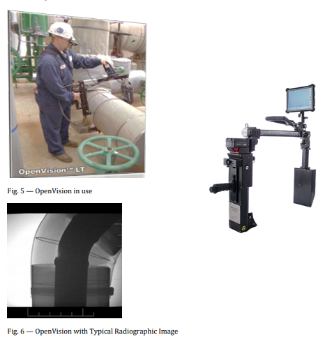
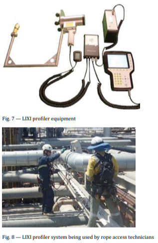
There are two types of systems capable of performing real time CUI scanning. One is the OpenVision and the other is the LIXI Profiler. The OpenVision is a small low energy x-ray unit, while LIXI uses a low energy radiation isotope as the energy source. Both essentially achieve the same result, in that both can detect real loss of wall thickness caused by CUI, but both methods are semi-quantitative and therefore need to be supported by an additional verification technique i.e stripping for visual assessment. These radiographic methods are used for rapid scanning of large volumes of both straight pipe sections as well as bends. They can be deployed using rope access technicians, thus making it a cost-effective inspection, by minimising the need for expensive scaffolding to gain access to elevated piping. These methods are restricted to inspection of piping, and both have a maximum practical pipe diameter capability of 300mm. Only external corrosion can be seen using OpenVision
OpenVision system
The OpenVision system being used by an operator is shown in Figure 5 and a typical radiographic image output is shown in Figure 6.
LIXI profiler
The LIXI profiler equipment is shown in Figure 7 and operators using the LIXI profiler can be seen in Figure 8.
Electro Magnetic Induction- Bracelet
This method uses a transmitter and receiver coil to generate an electromagnetic field between these sensors (Figure 9). This field travels through the thickness of the material up to a maximum of 12 mm and is primarily used for scanning of insulated piping. The method uses 8 channels, each in absolute and differential mode. This means that a large footprint can be covered with each scan. The Bracelet is wrapped around the external surface of the insulation (Figure 10) and has easy travel wheels to make pulling it along the pipe as smooth as possible to minimisesensor lift-off or bounce. Each track scanned is encoded so any wall loss detection as a result of CUI can be easily identified for further investigation and verification. The Bracelet is moved around the pipe circumference to obtain full 360° coverage.
This technique can only be used on carbon steel piping with non-ferrous cladding material, i.e., stainless steel or aluminium. The method cannot be used to scan piping that has galvanised steel cladding. The maximum insulation 8thickness that can be penetrated is 60 mm. This method can also be used to scan though fireproofing up to the same thickness. An example of a typical pipeline with a number of CUI defects is shown in Figure 11.

Pulsed Eddy Current
Pulsed eddy current (PECT) has been in use across industry for many years, and previously known as INCOTEST. Unfortunately, until recently the technique provided more questions than answers, often being referred to as “INCOGUESS”. However, in the last two to three years there have been significant improvements in this technology, especially with probe design and battery technology that has resulted in much more power being available to pulse the signals, increasing both detectability and reliability of the results. Like all techniques, if applied to the right application PECT can add significant value.
There are two types of systems available from separate manufacturers. This has led to the vast improvements and therefore this method has become more widely used.
Both systems perform similarly, but there are some small differences (because of the competition between manufacturers). In reality, they both achieve the same outcomes. These include:
- Detect corrosion under insulation and fireproofing.
- Penetrate up to 250 mm insulation and 100 mm steel.
- Not affected by “chicken wire” or reinforcing bar.
- Can scan insulated vessels, tanks, piping (including through fireproofing material).
- Ratio between insulation thickness (probe lift-off) and thickness of steel that can be penetrated.
- Cannot differentiate internal from external damage.
- Generally, cannot penetrate steel cladding material, so insulation must be stainless steel or aluminium (there are however developments taking place that will allow penetration through steel cladding materials).
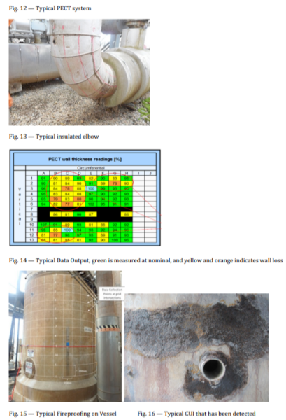
PECT works by using the principle of electromagnetic induction. An electromagnetic pulse is generated from the probe and this pulsed signal is transmitted into the steel being examined. The pulsed signal can easily travel through non-metallic insulation and fireproofing. Where a reduction of wall thickness is detected due to CUI, the pulse energy changes and the signal distorts, and this loss is measured as a percentage reduction from the initial nominal 9thickness set at the start of the inspection. The operator screen for a typical PECT system is shown in Figure 12. The images below show typical large diameter elbows marked up for PECT scanning.
Guided wave testing (GWT) – Long range guided wave (LRUT)
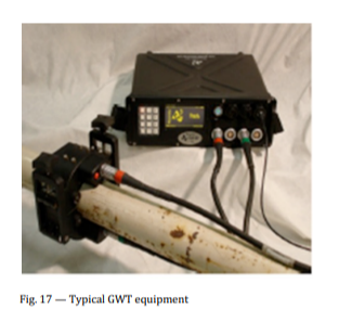
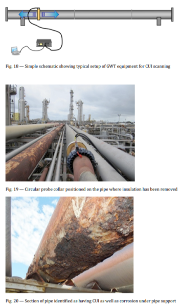
Long range ultrasonic guided wave scanning is a standard inspection technique that has proved itself over many years as an excellent method for the screening inspection of insulated piping, particularly for the detection of CUI as well as other process related (internal) defects. GWT can generally cover long lengths of piping from one single probe position, making it a cost-effective inspection technique for the detection of CUI. There are currently three main types of equipment and manufacturers, and all systems perform in a very similar way with similar data output.
GWT works by wrapping a circular probe array around the pipe. This may require some removal of the insulation. The system is then set up to send low frequency ultrasonic signals in both directions from the probe contact position. Reflected signals are then identified and these can come from “features”, i.e., welds, sockets, brackets etc., as well as from corrosion. The signals from CUI or corrosion can be separated from the features so a reliable test can be performed. In fact, the signal responses from the features can be very useful in determining the location of CUI corrosion, as well as confirming the distance that the signals have travelled along the pipe length.
GWT scanning does have limitations. For example, small, isolated corrosion can be missed and gradual thinning from erosion can also go undetected. But when this method is used as a screening tool for the detection and location of CUI, it can be very reliable.
Scanning at elevated temperature can be performed, but the cost of the high temperature ultrasonic sensors can make this application expensive.
Generally, several variables can influence the use of GWT testing and these include: coatings, wrapping, presence of yellow jacket (typical corrosion protection coating in gas or oil transfer pipelines), thickness of all coatings. Unfortunately, the influence of these cannot be predicted, which means that the effect on the reliability of the signals generated can only really be seen once an inspection is performed, as there is no guarantee that GWT will perform well each time it is applied.
Conclusion
CUI can be considered a serious issue, potentially going undetected and ready to cause a failure at any time. Well, there is hope; by understanding the causes, using engineering assessment and best judgement, and, with the combination of inspection techniques and developing a routine inspection strategy, unexpected failure from CUI can be minimised. Most, if not all inspection methods used to detect CUI without removal of the insulation are semiquantitative, so it is important to consult and work with inspection service providers to determine best technique combinations for your specific circumstance. Each method selected will have a POD (probability of detection) threshold, so it always important to use the highest POD method for your application, and this could differ from application to application.
New inspection methods that can address critical plant integrity issues like CUI are constantly being developed, however in most cases appear to be “variations on a theme” or minor modifications to other existing methods, and not all have been included in this paper. Unfortunately, there is currently “no silver bullet” to manage CUI, and until there is a “one size fits all” inspection method, we need to continue using the most appropriate methods that are currently available.
Finally, the equipment and method is only part of the process. All inspections need to be performed by experienced, skilled and well-trained inspection personnel, who fully understand the capability and more importantly, the limitations, of each technique. Without this, the prevention of failures from CUI may not be eliminated.
This paper is intended to give a brief overview of some of the inspection methods that have been used in the quest to locate and quantify CUI. They are all practical methods, however consultation with specialist service providers with regard to best fit inspection, is vital to optimising the defense against CUI. Research is on-going into ways to better inspect for the presence of CUI, and new techniques are always popping up, but for now unfortunately, there is no Silver Bullet.
REFERENCING
- Anon. (2017) HOIS joint industry project for NDT best practice in the oil and gas industry
- AS/NZ3788
- API RP 574 2016
AUTHOR DETAILS
Charles Perrie is the author of this paper. He is the Principal Consultant –Advanced Inspection at SRG Global Asset Care. He works across the Asset Care business supporting clients’ engineers to optimise their inspection budgets but at the same time maintaining a high level of integrity without compromising safety. He has held this position since 2010 and has worked in the same industry for over 40 years.