
This paper has been adapted from paper 45, Corrosion & Protection Conference 1997. The technology has moved on but we thought this may be of interest to those involved in cathodic protection of pipelines.
Author: H. Flitt
Author: V Gibson
Author: G.Rodger
Author: J. Christsen
Associated Company: Corrosion Specialists Pty. Ltd.
Author: P. Tomlin
Associated Company: AUSTA Energy
SUMMARY:
This paper will give an overview of the installation and commissioning of a cathodic
protection system on a 40km water pipeline buried within a high voltage transmission power line
easement. The pipeline was 900mm diameter and externally coated with polyethylene. Electrical
protection and possible earth fault current damage associated with pipeline installation will be
initially discussed. To obtain corrosion and electrical protection, the pipeline was segmented into
eighty seven electrically isolated sections. Electrical earthing was installed at each end of the
segments. Sacrificial magnesium rod anodes were considered the most cost effective method for
corrosion protection of the segments. The optimum anode dimensions and quantify for the final
system design was justified by using computer modelling. The commissioning of the system initially
was confined to anode potential and current measurements on each pipeline segment. To assess the
actual corrosion protection along the individual pipeline segments a pulsing method was devised.
Finally a computer management system was created to provide computer storage of the
performance data and site location information.
INTRODUCTION
During 1986, a severe drought was producing a water shortage crisis from the Bandora Dam. The dam is the water supply for
the Tarong Power Station and farms within the local area.. As power generation was in jeopardy, an emergency water supply
pipeline was rapidly built from Wivenhoe Dam to Tarong Power Station.
Half of the pipeline from Moore to Tarong Power Station is buried within the high voltage transmission line easement . Power line easements are ideal for utility corridors as they provide a means for distribution of products without land resumption and limit the environmental impact.
Buried pipelines are electrically insulated within the ground by applied surface coatings used for corrosion control. They are also electrically isolated from the ground in order to maintain a negative DC potential for cathodic protection. This electrical state provides the conditions for the establishment of dangerous AC voltages, on pipelines which parallel high voltage power lines within easements.
Fault conditions on high voltage lines can be responsible for damage of pipeline coatings, isolation flanges and electric shock hazards if neglected. Mitigation of these occurrences becomes an integral part of corrosion control of pipelines running parallel to high voltage transmission lines. Steady state powerline conditions, although less serious in magnitude, still require attention.
This paper is an overview of the installation of cathodic protection and electrical hazard mitigation on the power line easement section of the Wivenhoe to Tarong water supply pipeline.
ELECTRICAL INTERACTIONS ON PIPELINES
The three types of interactions (1) that occur with coated pipelines and high voltage transmission lines are as listed below.
• Electrostatic or capacitive coupling
• Electromagnetic or transformer action
• Resistive coupling or fault conditions
Electrostatic interactions are of concern during the pipeline construction phase. Stored coated pipelines placed in a nongrounded condition, in close vicinity of a transmission line, can become charged capacitively and produce a serious shock hazard.
Buried pipelines which parallel to high voltage overhead transmission powerlines are subject to induced voltages from the AC currents flowing in the cables. Pipe voltages occur due to the electric field transformer coupling between the three phase overhead conductors and the pipeline which is isolated from earth by the electrically insulating corrosion protective coating. If balanced or equal current flow occurs through the three phase conductors, the induced voltage is low as the induced field is the result of the unequal distances of the three conductors to the pipeline (2), (3).
Induced voltages will be considerably larger during transmission line fault conditions (4). Line faults occur if the conductors become earthed, suffer unbalanced loading conditions and take lightning strikes. High voltages are induced into the parallel sections of pipelines under these fault conditions.
The main factors that control the magnitude of the induced voltages are listed below.
• Separation distance of the power line from the pipeline.
• Pipeline coating electrical properties.
• Length of the parallel section of power line and pipeline.
MITIGATION OF ELECTRICAL HAZARDS
The NACE Standard RP0177-83, “Mitigation of Alternating Current and Lightning Effects on Metallic Structures and Corrosion Control Systems” presents procedures and guidelines for dealing with the proximity of overhead alternating current (AC) transmission lines to coated underground pipelines.
Mitigation methods that are commonly used are listed below.
• Separation of pipeline into small isolated sections.
• Supplemental grounding of the pipeline with sacrificial anodes or other grounding methods (5).
• Bonding of the pipeline to individual towers using polarisation cells.
• Installation of parallel mitigation wires bonded to the pipeline.
All of the above methods are aimed at reducing the induced AC voltages to acceptable levels
Overvoltage protection of insulated flanges, in close proximity to high voltage power lines, is maintained by installing isolator/surge protector (solid state devices) or polarisation cells which simultaneously provides DC isolation and AC continuity.
In addition, operators of pipelines must be protected from electrical shock by earth mats surrounding the valves which are connected to the pipeline. To receive a shock, the operator must be in good contact with the earth which is at a potential markedly different then that on the pipeline. The shock hazard is removed by earthing mats because the soil voltage on which the operator stands will be the same as that on the pipeline. The operators body is now not an electrical discharge path to ground.
PREDICTION OF PIPELINE AC VOLTAGES
The prediction of AC voltages on pipelines has been detailed by Kirpatrick (3). In undertaking predictions, the soil resistivity and coating resistance are considered the most important parameters. Computer modelling is commonly used for the prediction of pipeline induced AC voltages.
SYSTEM DESIGN
The pipeline easement section runs from the Moore township into the Tarong Power Station cooling dam for a distance of approximately 40 km. It contains two pump stations at Moore and Benarken and surge tanks are present at three locations. The majority of the pipeline is rubber ring jointed with some sections on steep grades fully welded.
To ensure electrical mitigation the pipeline was separated into 87 individual segments by removing the bonding strap over the rubber ring joint.
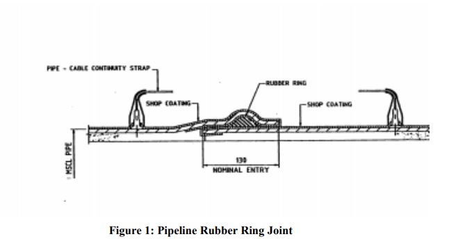
pipeline rubber ring joint figure 1
Figure 1 indicates the design of the rubber ring joint. The segments were less then 500m in length to adequately meet the required segmentation distance for fault conditions. Calculations of the induced voltages and the required
minimal separation distance were obtained from the transmission authority (Power Link).
Each pipeline segment had an earthing rod and magnesium rod anode placed at each end. A concrete covered pit was used to terminate the anode and earthing rod cables. Earthing mats were placed around every pit as given in Figure 2.
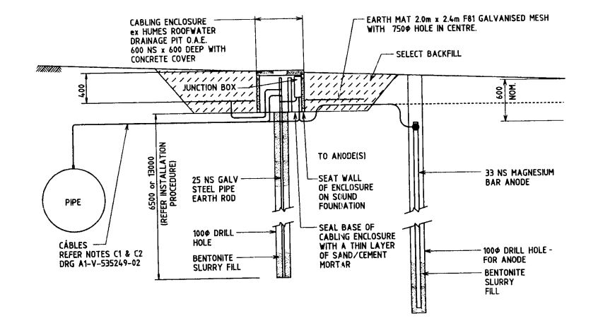
CP System Diagram-Figure 2
Water pipelines have the external attachments of air valves at hills, and scour valves in valleys. These takeoffs were isolated from the pipeline with a isolation flange and had a surrounding earthing mat for operator protection.
SYSTEM PERFORMANCE
To estimate the CP system performance as a function of soil resistivity a Windows computer program CPDESIGN was written in Visual Basic to generate the necessary design
parameters. Our aim was to ensure that we optimised the anode dimensions and the
number of anodes used. A number of authors (6), (7), (8) have outlined the methodology for these calculations which generally have the following five steps.
- Anode resistance is calculated from anode dimensions
- Estimation of driving voltage (anode potential – structure potential) for protection
- Anode current output
- Available structure current density for protection (anode current/steel surface area)
- Anode lifetime calculation.
By using the CPDESIGN program we were able to consider a large number of different variations of anode numbers and soil resistivity, to establish the optimal design. In step four the available current density must be greater than the required current, for protection of the structure to be a viable operating CP system
The design program initially calculates the anode mass and resistance from the input of the anode physical dimensions. Data obtained from CPDESIGN was used to generate performance graphs in an EXCEL spreadsheet as given in Figure 3.(missing)
The operational anode current is predicted at the intersect of the required current (straight lines) to protect a pipe segment having a given percentage of coating loss and the anode output current.
To calculate the anode resistance the input dialog box, from CPDESIGN as shown in Figure 4, is used. The Dwight equation was used to calculate the anode resistance values versus anode length. A plot of the resistance versus anode length is generated to indicate the relationship.
Figure 5 shows the main window for the program with a generated set of results. Current demand on a pipeline segment is calculate from estimates of protection current required for different soil conditions
SYSTEM INSTALLATION
Initially a site was excavated for the cable runs and the concrete pipe cabling pit. A mining blast drilling machine was then used to drill holes for the earthing rods and anodes. The earthing rods anodes were initially placed in the drilled holes and then surrounded with water saturated backfill. The resistance of the installed earth rod was measured to determine if secondary earthing was required. Once the resistance value was satisfactory the installation was completed.
SYSTEM COMMISSIONING
System commissioning consisted of initially measuring the protection voltage and anode current for each installation to determine segment performances. This was then followed by a more detailed assessment using a pulsed voltage on and off survey.
The pulsed survey of the segments is not straight forward as each segment has an uncoated earthing rod at each end. As the pipeline is coated with polyethylene the current leakage from the pipeline within a segment is extremely low.
The pipe essentially acts as an insulated cable linking the two earth rod installations which act as a relative large coating defects.
An interrupter and a battery were used to pulse from a segment start with the anode disconnected. The response was measured at the segment end with the installed anode still connected. The pulsing on voltage was set at 20 mV above that previously maintained by the detached anode. If the segment had current leakage problems the recorded voltage off voltage at the segment end was significantly lower then the potential recorded there when the segment had both anodes connected.
It was established from the pulsing survey that all segments were fully protected. Minor current drain problems were encountered with a small number of scour and air
valve attachments.
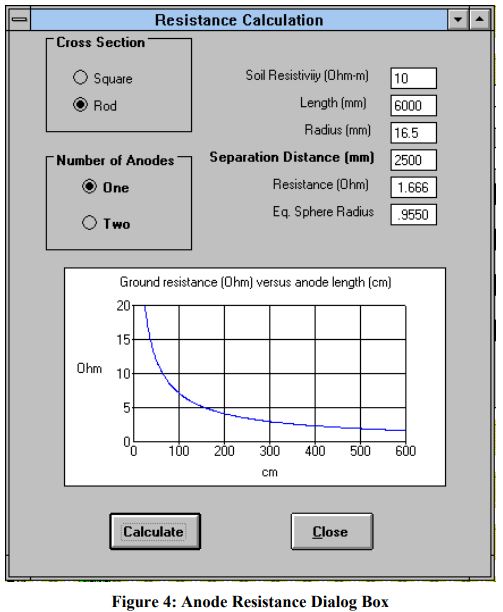
Figure 4
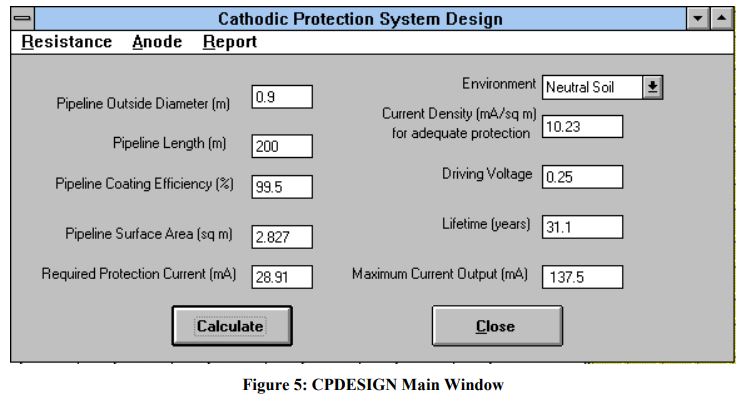
SYSTEM MAINTENANCE
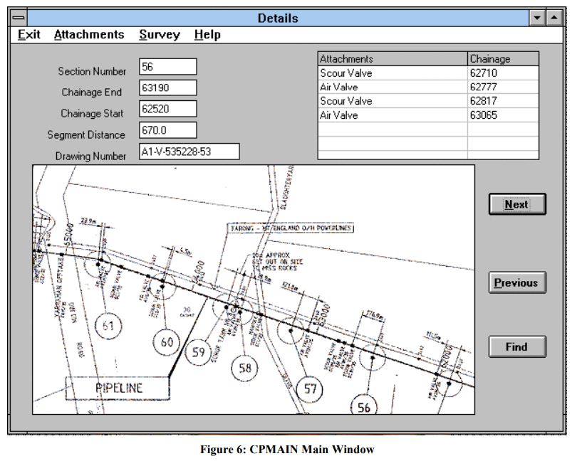
A Visual Basic Windows program CPMAIN was developed to manage future survey data from the pipeline CP systems. The program is essentially a front end to an ACCESS database which contains the monitoring records. Due to the large number of installations an electronic record was considered to be more efficient than a paper based filed system.
The main window of CPMAIN as shown in Figure 6 gives a map location with details on each pipe segment and the attachments present. By scrolling through the details of the 87 installations the pulsing survey data and attachment voltages are display as bar charts by selecting the menu options.
CONCLUSIONS
Due to the construction deadline imposed on the pipeline because of the pending water shortage to Tarong Power Station the provision of the cathodic protection system was undertaken in a relatively short time frame. In spite of this urgency an optimised cathodic protection system design and a correctly operating installation was provided to ensure the future reliability of the pipeline from external corrosion and electrical hazards. The development of software for design and maintenance of systems was extremely beneficial in meeting the time constraints of this undertaking.
ACKNOWLEDGMENT
The authors wish to acknowledge AUSTA Energy for permission to publish this paper.