 This article is adapted for the website from paper 52 at the Corrosion & Prevention 2004 .
Author: M Ali
Company:GHD Pty Ltd
Summary
Although cathodic protection (CP) to the above ground reinforced concrete structures was first applied around 30 years ago, the CP criteria for such application are still being researched. Among all the currently used CP criteria, the 100 mV potential decay criterion is considered to be the most pragmatic and generally achievable. There are some laboratory studies that suggest to formulate a “current density” criterion as a step forward. The current density requirement, however, decreases with time, to maintain the same level of polarisation/depolarisation such as 100mV decay.
The relationship between the current density and polarisation level & period is discussed in this
paper. Laboratory study results and the relevant data from an actual installation are presented. It is shown that the current density requirement to achieve a particular level of polarization decreases
with time as expected.
1. Introduction
Cathodic protection (CP) has now been recognised as the most viable option for controlling chloride ion induced reinforcement corrosion. The CP criteria however may still be considered as in developmental stage as research is being carried out to formulate more rational CP criteria (1,2). Although several CP criteria have been suggested in the literature, the 100mV potential decay criterion has been regarded by researchers and practitioners as the most rational CP criteria for the atmospherically exposed section of the structure (3-5).
The 100 mV potential decay criterion however is characterised by uncertainty in depolarisation as a function of time and sometimes of current density.
For example, Australian Standard 2832.5 (6) and British Standard (7) specify a potential decay over a maximum 24h of at least 100 mV from instant off. The Australian Standard also specify an extended potential decay criterion as “a potential decay over a maximum of 72 hours of at least 100 mV from the instant off potential subject to a continuing decay and the use of reference electrodes for the measurements extended beyond 24 hour”.
Regarding the extended potential decay, the British Standard specifies “a potential decay over an extended period (typically 24 h or longer) of at least 150 mV from the instant off subject to a continuous decay and the use of reference electrodes for the measurement extended beyond 24 hours. Because of the dependence of the potential decay criterion on the polarization period, Glass et al (2) suggested a current density criterion.
The current density criterion, however, is also dependent on the polarisation period. An attempt has been made in this paper to show the dependence of current density and polarisation level/period. Laboratory study results and actual data from an installation in NSW are presented in this paper.
2. Lab Study
2.1 Thest Specimens
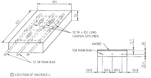
Figure 1 shows a test specimen used in the laboratory study. The specimens were 457mm x 305mm x 76mm slabs having:
• Three main steel bars;
• Three coupon steel bars, tied with the main steel bars, to assess the corrosion status of the main steel, and
• The macrocell steel.
In addition, macrocells were positioned in the mould one day before casting the main specimen.

Figure 1 Test Specimen Used in the Experimental Programme
The macrocells were cast as small cylinders with a short section of rebar (80mm long) centrally placed in each cylinder. A macrocell was 76 mm long x 51 mm in diameter. The macrocell steel diameter was equal to the main steel diameter (12.7 mm). With the exception of chloride levels (as indicated below), the macrocell concrete was identical to the main specimen concrete.
The macrocell steel was connected to the main reinforcement through a known external resistor. By measuring the voltage drop across the resistor, the magnitude and direction of the current flow between the macrocell steel and the main steel was determined. For example, when the positive voltmeter lead was connected to the main reinforcement, a positive voltage reading was indicative of the macrocell steel corroding (8). A negative sign would indicate that the net current flowing was from the macrocell steel to the main reinforcement, that is, the macrocell steel was receiving current from the anode system. NaCl was admixed with the mix water. The cement content of the mix was 325 kg/m3 and the water cement ratio was 0.56 by mass. The chloride content regime used in the test is shown in the following Table 1.
Table 1 Specimen Chloride Content and the Macrocell Chloride Content
[table “26” not found /]Anode mesh was placed appropriately positioned during casting of the specimens, as shown in Figure 1.
2.2 Establishment of Protection Current Density
All specimens were supplied with CP current 14 days after casting. Some of the specimens were kept as control (i.e., no CP current applied). The macrocell steel, which was surrounded by relatively higher chloride content than the main steel, had a more negative potential than the main steel. In this situation, a positive voltage drop across the resistor was noted when the positive voltmeter lead was connected to the main reinforcement. The reinforcement were then polarized with impressed DC current, connecting the positive terminal of the supply to the anode system and negative terminal to the main reinforcement.
The positive voltage drop across the resistor was reduced to zero by increasing the current. At this zero voltage drop condition, no local corrosion current flows between the macrocell steel and the specimen steel; the current passing to the specimen steel was the current required for adequate protection. The current density was then calculated as the applied current divided by the surface over of all reinforcement. The process was continued approximately once every two weeks for up to 180 days.
2.3 Effectiveness of CP
Effectiveness of the protection current density, established in the previous section, in terms of arresting corrosion was checked
using destructive testing. After the end of polarization (up to 180 days), the specimens were broken up to retrieve the coupon
and macrocell bars. The bars retrieved were physically inspected for corrosion condition. The weight loss was then calculated
as the difference between the final weight of the rebar after retrieval from the specimen and the original weight recorded before casting of the specimen; the result was expressed as a percentage of the original weight.
2.4 Protection Current Density
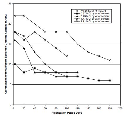
Figure 2 shows the protection current density required at different polarization period for the specimens having a chloride differential of 1.50 % (by wt of cement).

Figure 2 Current Density for a Chloride Differential of 1.50 % (Note: 0.37 stands for 0.37% chloride in the specimen,
1.87% chloride in the macrocell).
Data presented in the above Figure 2 suggests that
• The CP current density requirement ranged between 6.0 and 22 mA/m2
of steel surface area;
• For a higher chloride differential present within a specimen, a higher current density is required for adequate corrosion
protection (for example, a higher chloride gradient is present in 0% chloride bearing specimens compared with 0.37%
chloride bearing specimens. Higher current density was required for the former case).
• The current density requirement depends both on the general chloride content in the specimen and the extent of
chloride rich pockets present within the specimen (for example, higher protection current was required for the higher
chloride bearing specimens such as those containing 1.47% chlorides and 2.91% chlorides).
• The current density requirements decrease with the increase in polarization period
The dependence of the protection current density on the chloride differential within a specimen is ascribable to the higher
potential of the steel in the high chloride bearing macrocell concrete. More protection current is required for current reversal,
i.e., to overcome the high potential gradient. CP current causes the migration of chloride ions away from the steel (9). With
increase in applied current, more chloride ions moved away from the steel surface resulting in a decrease in current density
requirement with polarization time.
2.5 Effectiveness of Current Reversal Technique
The effectiveness of the current reversal technique in determining protection levels was assessed from the weight loss data of the coupon steel and macrocell steel.
The weight loss data are presented in the following Table 2.

The results presented in this Table suggest that macrocell steel lost relatively more weight than the coupon steel which is considered to be attributable to a relatively higher chloride presence in macrocell steel. The results in this Table also suggest that the CP technique significantly controlled chloride induced corrosion.
3. Actual Installation Results
The current density requirement for achieving a 100 mV potential decay criterion on a reinforcement concrete wharf structure in Newcastle, NSW, Australia is presented here. A ribbon anode CP system was installed to the front beam soffit of the Western Basin wharf 3 in 1998. There are two sections for the Western Basin Wharf No. 3.
• Between southern End & Joint 1 (120 m)
• Between joint 1 & joint 2 (108 m)
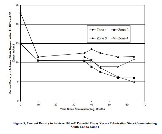
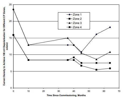
There were four CP zones for each section. Figures 3 & 4 show the current density requirement at different period since commissioning for the above mentioned two sections of the wharf.


Figure 4: Current Density to Achieve 100 mV Potential Decay Versus Polarisation Since Commissioning:
Joint 1 to Joint 2
Data presented in Figures 3 & 4 suggest that
• The CP current density for achievement of the required CP criteria (of say 100 mV decay) was generally less than 20
mA/m2 although a current density higher than 20 mA/m2
was required initially.
• The initial current density varied between 15 mA/m2
and 23 mA/m2.
• When the data for the first year of operation is disregarded, the current density requirement ranged between 5 and 18
mA/m2.
• The CP current density requirement generally decreased with increase in polarisation period.
4. Conclusions
• Conclusion of the lab study are limited to the testing regime used, i.e., chloride content in concrete of 0 to 2.91 % by
wt of cement and the chloride differential within concrete of 1.50 % by wt of cement
• The CP current density requirement found in an actual installation and in the lab study are within the current density regime used in CP design (i.e., within 20 mA/m2 generally used in CP design)
• The laboratory study suggests a CP current density requirement between 6 and 22 mA/m2
of steel surface area. The initial current density on the actual installation ranged between 15 and 23.mA/m2.
• Both the lab study and the actual installation results suggest that the current density requirement decreases with increase in polarisation period. Such trend is beneficial for the CP system components, i.e. the CP system components
will get less stress (i.e. the backfill will have less acid generation) when the CP system get aged.
• It should be possible to formulate a CP criteria based on current density and activation period. However more lab research and use of the data from actual installations are required.
5. Acknowledgement
The author wishes to acknowledge the late Professor Rasherduzzar for his valuable contribution in the lab study. Permission of Newcastle Port Corporation for publishing the results is acknowledged. Acknowledged is also due to GHD Directors for financing the author to present this paper.
6. References
Glass, G K, “Technical Note: The 100 mV Potential Decay Potential Cathodic Protection Criterion”, Corrosion, Vol. 55, No. 3, March 1999, pp 286-290.
Glass, G K, Hassanein, A M and Buenfield, N R, “Improved Basic for Cathodic Protection Criterion and Its Application to Reinforced Concrete”, 14th International Corrosion Congress, Cape Town, September 1999.
Stratfull, R F, and Mannings, D G, “Evaluating the Performance of Cathodic Protection Systems on Reinforced Concrete Construction:, Alan P Cane Edited, Society of Chemical Industry, London, England, p287, 1983.
Wyers, R E, and Cady, P D, “Cathodic Protection of Concrete Bridge Decks”, ACI Journal, Proceedings, Vol. 81, No.6, Nov-Dec 1984, pp 618-622.
Ali, M G, “Criteria for Cathodic Protection of Steel in Concrete in the Context of Arabian Gulf Environment”, PhD Thesis, KFUPM, October 1991.
AS2832.5, the Australian Standard Cathodic Protection of Metals Part 5 Steel in Concrete Structures, 2002.
BSEN 12696:2000, the British Standard on “Cathodic Protection of Steel in Concrete”, 15 June 2000.
Schell, H C, and Manning, D G, ”Evaluating the Performance of Cathodic Protection Systems on Reinforced Concrete Bridge Substructures” Materials Performance, July 1985, p18.
Ali, M G, Rasheeduzzafar, and Saadoun, S A, “Ion Migration in Concrete Due to CP Current”, Cement and Concrete Research Journal, Vol. 22, No. 1, Jan 1992, pp 79-94.