Author: Bruce Ackland
This paper was presented at Corrosion & Prevention 2023.
ABSTRACT
A recent inquiry about galvanic corrosion of an estimated 35,000 tonnes of chemical and conventional warfare artillery ammunition dumped on a Belgian sandbank immediately after WWI revealed numerous analogies with various phenomena encountered in cathodic protection. Typical cathodic protection anode output methods were used to calculate the possible range of corrosion rates for the zinc alloy comprising the fuze when connected to the steel shell and brass or, at the end of the war, steel cartridge, when placed directly into seawater. A reduction in corrosion rates to more realistic values was needed due to concretions formed in the seawater and sediments, and due to the calcareous deposits typical of those formed on cathodically protected steel in seawater. This paper highlights some of the cathodic protection principles used and regularly digresses to discuss these analogous and similar phenomena.
Keywords: Cathodic protection, Steel, Seawater, Calcareous deposits, Concretions
Introduction
Mankind has been using the world’s oceans as a tip for rubbish, waste, toxic substances and dangerous materials for thousands of years. It is truly extraordinary to this author that one of the first international efforts to regulate ocean dumping was not until 1975 when the Convention on the Prevention of Marine Pollution by Dumping of Wastes and Other Matter, commonly called the “London Convention”, was first ratified by 15 nations. Prior to 1975, there was almost nothing that could not be legally dumped in the ocean, other than restrictions imposed by local environmental authorities of the coastal state.
Imagine the dilemma after the first world war, when European nations had over a million tonnes of unwanted munitions such as high explosives and chemical warfare artillery shells that required disposal. The oceans cover about 71% of the earth’s surface and it seems endless. No worries, into the sink it goes! More than a billion artillery shells were fired on the Western Front alone [1]. Enormous stockpiles remained at the end of the war and the huge amounts of chemical and other warfare munitions needed safe and secure disposal. The extreme danger presented by any efforts to disarm hundreds of thousands of shells meant the only option considered practical at the time, especially for the CWA munitions that could not be disposed of safely using controlled explosions, was to dump them in the ocean. Millions of shells, grenades, mortar bombs and the like also landed without detonation (estimates are that up to 30% of shells failed to explode) and approximately 200 tons of munitions are still being recovered each year by Belgium’s bomb disposal unit, DOVO, throughout what was part of the Western Front [2]. In the past, those articles unable to be disarmed or safely destroyed were usually added to the stocks dumped in the sea.
This dumping then continued beyond the second world war, with further ocean dumping continuing well into the 1970’s. Even Australia was not immune to being used for dumping munitions with at least 21,030 tons of Chemical Warfare Agents (CWA) being dumped off the coast of Queensland, NSW and Victoria between 1946 and 1970 [3], where they remain to this day.
All of these dump sites around the world pose a risk to all sorts of marine activities such as fishing, laying pipelines and cables, port constructions (many sites are close to shore), dredging, sea bed mining and any other activity that may make contact with the munitions. All of the munitions will corrode and will eventually leak sooner or later, creating a risk of contact with people, marine life or other environmental harm.
Earlier this year, the author was copied into an inquiry from AMACORT, the corrosion research group of the Antwerp Maritime Academy (AMA) about the likely corrosion rate of the zinc fuze (the bit at the top that causes detonation) connected to the shell often containing CWA of a particular artillery projectile called an “E.K.Z.17” when placed in seawater. This question was on the periphery of extensive work being conducted by the AMA and other groups, including Australian collaborators studying corrosion of shipwrecks and other wreckage, particularly in the Belgian North Sea [4, 5]. Later, the inquiry extended to include the effect of a brass cartridge and broadened into discussions about natural factors that would reduce the corrosion rates, especially when buried in marine sediment.
The inquiry related specifically to the dump site on the Paardenmarkt (in English, “horse market”) sandbank, near the town of Knokke-Heist in Belgium, adjacent to the Port of Zeebrugge; simply called the Paardenmarkt Bank. The location is highlighted in Figure 1 amongst other known dumping sites in the OSPAR Convention area [6].
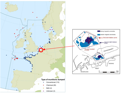
Figure 1. Location of known munitions dumping sites. The Paardenmarkt sandbank site is shown circled red. [6]
An estimated 35,000 tonnes of mainly unused German artillery shells were dumped at Paardenmarkt Bank in 1919 and 1920 [7]. A large proportion contained CWA such as phosgene, diphosgene, chloropicrin, mustard gas, Clark (arsenic compound), chlorine, etc. They were largely forgotten until 1971 when dredging work struck some obstacles and subsequently, navy divers identified chemical shells in the area. The present-day protocol for these types of sites is not to disturb them at all, to advertise their location, prevent access and monitor.
Excellent phenomenological models exist for the marine corrosion of mild and low alloy steel [8, 9], which describe the various stages of corrosion activity through to periods of up to about five years. Extrapolation of these models out to the very long exposure times for shipwrecks and other wreckage can indicate an over-estimation of the corrosion rate of perhaps 2-3 times [4, 5]. The likely reason given for this is the formation of concretions that present additional constraints to the corrosion process. This disparity is consistent with observations [10] that often the only way to accurately assess the very long-term corrosion rates (e.g. 50+ years extending out to centuries) is to use data obtained from ship wrecks that have been in the water for very long periods of time.
The investigations and modelling of shipwreck corrosion is often based on single material items, such as steel, cast iron, bronze, copper etc. Artillery shells are composed of multiple metals and alloys for the fuze, shell and cartridge [5], adding galvanic corrosion activity into the mix. Although the literature contains some excellent discussions about the fortuitous “cathodic protection” of metal artefacts in contact with dissimilar metals [10], the increase in corrosion rates of the anodic material of a galvanic couple is not well studied.
This paper discusses how cathodic protection (CP) knowledge can help explain some of the observations and describes some of the CP analogies with the corrosion and protection phenomena of marine artefacts, including munitions. The corrosion rates suggested here are used for comparative purposes rather than absolute numbers and as a guide to understanding the factors that affect the galvanic cell’s long-term behaviour.
The Problem and Some Background Electrochemistry
The ammunition in question is a German 77 mm Lg.F.K.Gr. artillery shell with an E.K.Z. 17 fuze which was one of the more common types believed to be located at the Paardenmarkt site. Figures 2 and 3 show the typical dimensions and composition of the particular configuration considered here.
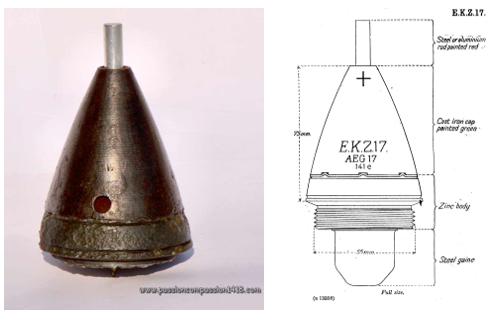
Figure 2. E.K.Z.17 artillery shell recovered from Belgium soil including fuze details and dimensions; excluding the shell and cartridge [11].
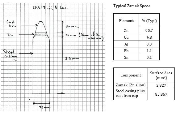
Figure 3. E.K.Z.17 shell casing, fuze dimensions and typical specification.
There was another type of E.K.Z.17 with the full nose cone being Zamak, but for now this paper will just consider the configuration shown in Figures 2 and 3 with the Zamak ring and cast iron cap.
The zinc alloy known as Zamak was typically around 90% Zn alloyed primarily with Cu, Al and Pb, with other elements being added or as impurities contained in recycled scrap metal. The actual composition varied substantially depending on the availability of raw materials during the war. In this paper, the use of the words zinc and Zamak will tend to be used interchangeably when discussing the ammunition, knowing that the “zinc” being discussed in context is the Zamak alloy.
The zinc will be anodic relative to the cathodic steel casing of the shell and cast-iron nose of the fuze, with an anode:cathode area ratio of about 1:30. It was understood that this galvanic couple (Zn/Fe) will most likely accelerate the corrosion rate of the zinc. The question was, by how much and how fast?
There is some uncertainty about what the alloying elements will do to the zinc electrochemically, but it has been assumed it will remain active (subsequent private communication has confirmed this). The primary zinc anode corrosion product usually seen for galvanic CP zinc anodes is zinc chloride which hydrolyses to zinc hydroxide and these products do not add any practical resistance layer to zinc anodes. The zinc hydrolysis will reduce the local pH at the zinc by the typical overall chemical reaction,
![]()
This is assumed to be the case for the E.K.Z.17 zinc alloy.
Aerobic conditions will predominate in the seawater and there may be anaerobic conditions in the silt, but reaction (1) is not dependant on oxygen availability.
The primary cathodic reaction (2) on the steel,
![]()
is of course completely dependent upon the availability of oxygen to replace that consumed.
The pH at the surface of a steel cathode is always substantially higher than the bulk solution, a fact shown in Figure 4 [12], where the pH rises dramatically very close to the cathode surface.
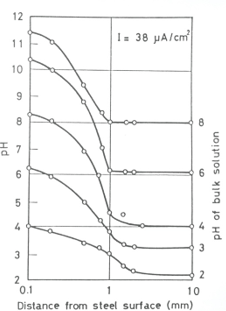
Figure 4. Variations of pH with distance from the steel surface cathodically polarised at 38 µAcm-2 in 3% NaCl solutions with various bulk pH [12]. Seawater has a pH of around 8 and so a pH of around 11.5 would be expected at the current densities shown and at least 12 after prolonged cathodic action (e.g. days). [12]
The increase in pH is a simple outcome of the cathodic reaction in Eq. (2), or when the oxygen is consumed and the potential is sufficiently negative under neutral and alkaline conditions,
![]()
It is important to note that the hydrogen produced by reaction (3) will not start to impact on the process at pH of say 12 until a potential of at least -0.96 VAg/AgCl/sw [13] or more negative is reached. The steel cathode cannot be polarised more negative than the zinc alloy potential which is about this value anyway and therefore, during this discussion only reaction (2) will be relevant for the cathode and the availability of oxygen will be of particular importance.
The First Question
The initial inquiry was to estimate, roughly, the corrosion rate of the zinc part of the fuze galvanically connected to the steel casing (containing the CWA), when exposed directly to seawater. Corrosion of the zinc will eventually expose the CWA to the environment. The presence of a brass or steel cartridge containing the initial propellant for the ammunition was initially excluded, because it was not known whether this component had sometimes been removed before disposal. Brass was used for the cartridge during the early stages of the war but as base material supplies ran short, then steel was more common. The dumped ammunition was most likely to have been manufactured during the latter stages of the war and so are more likely to have steel cartridges. The view of this author is that the most probable situation is the whole of the munition was dumped due to the hazard associated with tampering with it before dumping; they just wanted to get rid of the stuff. The addition of the cartridge will be dealt with later, but for the moment the problem to consider is just the action between the Zamak and the steel casing.
It was decided, based on the geometry and dimensions of the shell shown in Figure 3, that the easiest and probably most realistic way to estimate the corrosion rate was to consider the zinc ring of the E.K.Z.17 to look very much like a bracelet anode commonly used for cathodic protection of offshore pipelines. The CP industry has standard formulae for calculating exactly this type of thing.
The zinc presents itself on the outside as a ring and so can be modelled like a bracelet anode on a short steel/iron pipe. The surface area of the zinc ring is about 2,827 mm2. The geometry isn’t exact but these are close enough. A common standard formula for the resistance R (Ω) of a bracelet anode through the electrolytic path to the cathode is [14, 15];

where 𝜌 (Ωm) is the electrolyte resistivity and A (m2) is the surface area.
Eq. 4 was originally developed by an Australian, L.T. Ryan in the early 1950’s [16], based on empirical testing in the laboratory and confirmed in site trials and full-scale installations.
Ryan used old pump casings and engine blocks as impressed current anodes for the Lae wharf in New Guinea (as it was then). Ryan’s equation produced remarkably good correlation with the actual site measurements and prior laboratory verification work as shown in Table 1.
Table 1. Experimental verification of Ryan’s equation for different shaped anodes [16].
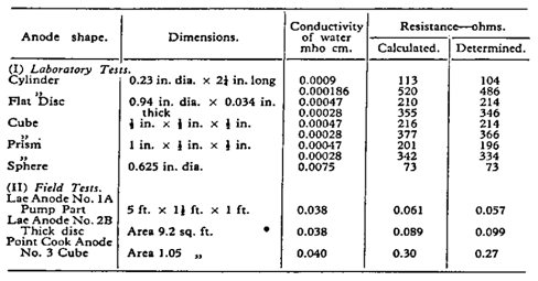
Ryan’s work will be discussed in more detail during the presentation.
Assuming a seawater resistivity of 0.25 Ωm and using the surface area of 2,827 mm2 (2.827 x 10⁻³ m2), the resistance of the zinc ring is then 1.48 Ω using Eq. (4). The smaller resistance of the cathode within the circuit may be ignored for now because this will be offset, more or less, by the fact that the anode (Zn) and the cathode (steel/iron) are not remote from each other. Moving the anode and cathode close to each other will reduce the circuit resistance, while the cathode has a finite, contributing resistance. Suffice to say, the approach tends to be a bit heuristic but yields pretty good results in the field with CP anodes in general and is a common approach used in the industry.
The current through the cell will depend on the closed-circuit potential difference (driving voltage) between the zinc and the steel/iron. This would normally be around 300-400 mV for regular zinc anodes and steel in seawater initially, rapidly falling to maybe 100-200 mV once the cathode has polarised.
If the early driving voltage is, say 100 mV, then the current in the galvanic cell will be 0.1/1.48 = 0.068 A. This converts to a current density on the zinc with surface area 2.827 x 10⁻³ m2 of 24.05 Am-2. Using the equivalence of current density for zinc of 1 Am-2 = 1.5 mmy-1 (Faraday’s Law for zinc), then 24.05 Am-2 will result in a theoretical corrosion rate of 24.05 x 1.5 = 36.1 mmy-1 (!). This is an extraordinarily high corrosion rate and the zinc component of the fuze would disappear very quickly if that rate persisted in seawater, but polarisation will continue at these high current densities and a number of other important factors will reduce this corrosion rate to more realistic values. For the moment, let’s continue looking at the very initial conditions immediately upon immersion in seawater when these very high current densities are plausible.
Early Polarisation
The zinc will polarise, but to a lesser extent than the steel. This is mainly a result of concentration polarisation occurring at the cathode due to oxygen transport being limited, but there is no such reliance on oxygen availability for the anodic reactions to proceed. The polarisation of the cathode is controlled by the oxygen availability through reaction (2).
Continued polarisation of the cathode will reduce the driving voltage and hence the galvanic cell current is predominantly determined by the transport of oxygen to the cathodic site. The rate at which the oxygen can reach the cathode surface is probably the most important feature of the entire process. Almost everything else that occurs, ranging from the formation of calcareous deposits and concretions to the structure of the sandbank impact on the availability and transport rate of oxygen to the cathode.
Oxygen consumption at the cathode surface will begin immediately when the galvanic couple are connected and in the water. Although there is plenty of oxygen in the bulk seawater, transport through the thin diffusion layer adjacent to the cathode surface is nonetheless restricted to some extent.
The current density on the steel/iron cathode with a total surface area of 85,867 mm2 (including the cast iron cap and the base of the casing) at the earlier 100 mV driving voltage is 0.79 Am-2. This is a very high current density on the steel/iron cathode from a CP perspective (compare with the initial CP current requirement of 0.17 Am-2 from DNV-RP-B401 [14], developed for North Sea conditions) and it would be expected to strongly polarise, especially after developing a calcareous deposit on the cathode, which will begin almost as soon as the current is applied [17-19]; a phenomenon to be discussed in more detail. If the driving voltage is reduced down to say 10 mV due to this initial strong polarisation, then the current density on the zinc would be 2.4 Am-2, converting to a corrosion rate of 3.6 mmy-1. This is still a very high corrosion rate. The cathodic current density on the steel would be 0.079 Am-2; still in the range of full CP once polarised.
Calcareous Deposits
The pH at the surface of the cathode will be highly alkaline as described earlier due to the cathodic reaction (2). Calcium carbonate CaCO3 and magnesium hydroxide Mg(OH)2 will precipitate out onto the cathode surface at the elevated pH to form a calcareous deposit that restricts the transport of oxygen and adds to the circuit resistance [17-19]. The main allotropic form of CaCO3 is aragonite since the presence of Mg2+ ions inhibit the formation of calcite. The only allotropic form of Mg(OH)2 is brucite. The aragonite starts to precipitate at about pH > 8 (the pH of seawater is typically 8), while brucite appears at around pH > 9.5. There may also be small amounts of MgCO3 in the deposits.
The proportions of these two substances, CaCO3 and Mg(OH)2 primarily depends upon the current density and cathode potential, with aragonite predominating at moderate CP potentials (-0.8 to -1.0 VAg/AgCl/sw) and brucite from around -1.0 VAg/AgCl/sw or more negative [20].
The presence and action of these calcareous deposits has been long known. For instance, Davy [21] reported the presence of the calcareous deposit in 1824 (“carbonated lime and hydrate of magnesia”) when the very first cathodic protection system was applied to protect the copper sheathing of timber hulled vessels using iron and zinc anodes. Cox [22] gained a patent in the US for the cathodic production of the calcareous deposit and Humble [17, 23] described in detail the early understanding of the current densities required to produce different proportions of the two components.
It was also recognised very early on [17] that the primary protective action of the calcareous deposits is to; (i) act as a barrier to oxygen or other depolarisers, (ii) increase the internal resistance of the local corrosion cells and (iii) increase the pH of the water film in contact with the metal surface above that of normal seawater.
The formation and action of calcareous deposits is also well understood in marine archaeology where galvanic coupling is known to reduce the corrosion rates on the cathode [10]. The deposits also form a good base for a dense layer of concretion development (dealt with in the next section) which in total reduces oxygen transport and adds resistance to the galvanic cell circuit [10, 24]. Cathodic protection is also known to be an effective method of site stabilisation of corroding artifacts and wrecks [25].
The presence of the calcareous deposit allows the CP system output to be reduced since a lower current density is required to maintain good levels of polarisation. For instance, DNV-RP-B401 [14] (applicable for the North Sea) recommends the initial current density for bare steel in depths up to 30 m in temperate climates of 0.20 Am-2 may be reduced to 0.10 Am-2 once polarised to protection potentials. Similarly, AS 2832.3 [26] recommends 0.12 Am-2 initially and 0.090 Am-2 to maintain polarisation in SE Australia (0.12 Am-2 and 0.065 Am-2 respectively in NW Australia). An example of the reduction in current requirements needed to maintain three different fixed potentials is shown in Figure 5 [18].
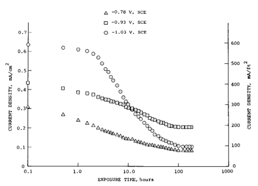
Figure 5. Current density versus exposure time for three potentials and 31 cm/s velocity in seawater [18].
Figures 6 and 7 show two examples from the author’s experiences of typical calcareous deposits on wharf structures in tropical and temperate seawater in Australia. In each instance the calcareous deposits have reached up to about ¾ tide height.
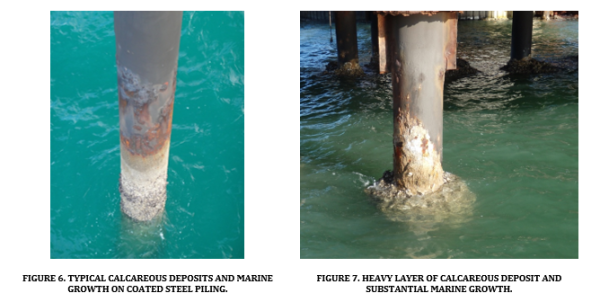
The deposits can enhance the adherence of marine growth, depending on the local water nutrients, creatures, plants and current densities (or ratio of anode to cathode areas for galvanic systems); the latter being a feature highlighted by Davy way back in 1824. Fig. 7 shows how the calcareous deposit can become very thick and the marine growth quite substantial. The metal is protected beneath these deposits, (one can chip a bit off and check) although it tends to be marginal where it starts to thin out in the upper tidal zone. The deposits provide an excellent surface for marine organisms to colonise (molluscs, coral, etc) and plants (seaweed, etc) to accumulate.
In relation to the Paardenmarkt situation, the expected current densities during at least the early stages of immersion would have generated a calcareous deposit and the long term cathodic current densities too should allow it to be maintained or enhanced. It is likely that the early formation of the calcareous deposits on the steel cathode surface helps maintain an alkaline pH and should lack any substantial iron corrosion products. CP is usually effective because it creates a local environment that is conducive to passive behaviour [27], resulting in negligible corrosion rates. There may therefore still be some iron oxides and hydroxides present, but in small quantities and with compositions typical of passive conditions. This process will ensure cathodic protection is maintained on the steel.
Although the calcareous deposit forms on the cathode, it will have a direct effect on the zinc corrosion rate by the combination of reducing the driving voltage of the cell through concentration polarisation (restricting the transport of oxygen to the cathode) and increasing the circuit resistance.
So, based on the typical reduction by half in current density needed in CP to maintain protection levels, then it may be reasonable to allow for say halving of the galvanic current in the ammunition corrosion cell. In this way, it might halve the Zn corrosion rate to perhaps 3.6 mmy-1 ÷ 2 = 1.8 mmy-1.
Concretions
A common observation on metallic artifacts resting in oceans and seas around the world is the development of marine concretions. These readily form on steel and iron artifacts as a result of marine organisms depositing calcium carbonate and other material into a cement like materials over the metal surface [28]. Copper and its alloys are less affected due to the toxic nature of copper to many organisms but they still form, depending on the environmental circumstances, but usually have a different structure on different metals and alloys [24]. A typical generic concretion layer cross section on metal is shown in Figure 8 [10].
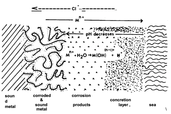
Figure 8. Typical cross section through a concretion layer formed in seawater [10].
The cross section in Fig 8 serves to illustrate the complex nature of the different layers. The pH at the zinc anode metal surface will most likely be acidic and the concretion layer will help contain the zinc corrosion products that might otherwise slough off. The zinc will therefore probably have a mixed layer containing zinc corrosion products and an acidic local environment overlain by the typical alkaline calcareous concretions.
For the galvanic cell at the Paardenmarkt, the first layer immediately in contact with the steel components will be the cathodically generated calcareous deposit which starts to form almost immediately upon immersion, as noted in the previous section. The CP calcareous deposits will then be overlain and intermixed with calcareous concretions with the passage of time.
The addition of concretions over both the anode and cathode will increase the cell resistance (it must because it adds an ohmic resistance to the circuit, although the actual value is unknown and difficult to estimate), restrict the transport of oxygen to the cathode and also slow the diffusion of ions, reactants and products at the anode. The combined effect will be to slow down the overall corrosion process.
If the concretions result in a general overall reduction in corrosion rate by about 1/3 when added to the long-term estimates as noted earlier, the zinc corrosion rate then comes down to perhaps 1.8 mmy-1 ÷ 3 = 0.6 mmy-1 during immersion after all of the above considerations are taken into account.
Sediment/Silt Resistivity
Burial in the silt or sediment will have several direct effects. The resistivity will be an order of magnitude higher than the seawater and so the galvanic current and hence corrosion rates from that alone will reduce by a factor of ten at least. Personal experience shows a typical sea bed resistivity of about 2-3 Ωm, compared with normal seawater of about 0.2 to 0.3 Ωm. This would bring the Zamak corrosion rate down to about 0.06 mmy-1 at the driving voltage of 10 mV at times when buried, but rising to about 0.6 mmy-1 when exposed directly to the seawater.
The steel would not be expected to corrode to any significant extent, being effectively cathodically protected due to the increase in pH at the cathode, polarisation to relatively negative potentials and maintenance of the calcareous deposits which would likely create passive conditions with consequential low or negligible corrosion rates.
The ammunition would have first rested on the sandbank and sunk into the sediment at some stage (this is known to occur here and a prime reason why the site was originally chosen). Water pattern movements, local dredging and other port related activities have caused the sand bank to change over the last 100 years and local reports are that the ammunition has been exposed for about 60% of the time. If just the various factors considered above are used, then it might be expected that the loss in Zamak thickness would be about 0.6 mmy-1 x 62y + 0.06 mmy-1 x 31y = 39 mm. Even if this turns out to be a very rough estimate, then the ammunition would most likely be at significant risk of leaking or would have already leaked.
Cartridge
A final complication is the inclusion of the cartridge containing the propellant. This was usually brass or later steel when copper was in short supply. The brass might normally be expected to increase the galvanic current since the open circuit potential difference between brass and zinc is greater than between the steel and zinc. However, it is the closed circuit potential difference that determines the cell current.
Polarisation of the cathode, either steel without the brass cartridge or the steel/brass couple, in contact with the Zn, will depend on the electrochemical characteristics of the various components. For example, Hildebrand et al [29] have shown that, at least in tap water, copper can cathodically polarise more easily than steel with a subsequent reversal in potential difference as an externally applied current density is increased. In their work, this reversal occurred at a current density of 0.025 mAcm-2 (0.25 Am-2) applied to a steel/copper couple with a steel:copper area ratio of 56. Although their work was in tap water, the cathodic polarisation of a steel/Cu couple, or more importantly a steel/brass couple in seawater may well display similar features which are yet to be determined.
The anode:cathode area ratio will also impact on all if this. Also, if the cartridge is steel then this would reduce the anode:cathode area ratio and therefore could still exacerbate the problem.
The added effects of the brass or steel cartridge is the subject of ongoing research and additional details will be discussed during the presentation.
Corrosion Rate Calculations
When estimating the corrosion rate of galvanic anodes for CP, the actual consumption rate is always greater than the theoretical rate (i.e. based on Faraday’s Law) by about 10-20%. This is usually considered to be a result of the normal self-corrosion of the zinc adding to the corrosion rate using the cell current. For instance, AS 2239 [26] uses a practical consumption rate for zinc galvanic anodes of 12 kgA-1y-1, whereas Faraday’s Law puts it at 10.7 kgA-1y-1. DNV-RP-B401 [14] uses 11.2 kgA-1y-1 in seawater and 12 kgA-1y-1 in soil, while ISO 15589-2 uses 11.2 kgA-1y-1 in seawater and 11.7 kgA-1y-1 in seawater sediments.
The corrosion rates presented here are used simply to illustrate some of the important factors that will impact upon the actual circumstances. For simplicity, this paper has just considered the assumption that Faradays Law will provide a fair estimate of the corrosion rate based on the galvanic current, understanding that an additional 10-20% may be added if necessary.
Possible Progression of Corrosion and Final Comments
If each of the above factors are progressively taken into consideration then the impacts upon the possible long term corrosion rates of the zinc might look something like Figure 9.
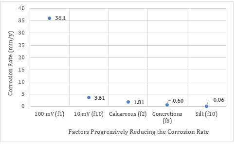
Figure 9. Possible impact of various factors upon the zinc corrosion rate in the galvanic cell of the ammunition.
The number after the “f” represents the reduction factor for that particular event. The factors discussed have been the initial polarisation as oxygen is consumed at the cathode (f10), the development of calcareous deposits (f2, affecting oxygen diffusion and cell resistance), formation of concretions on the anode and cathode (f3, affecting oxygen transport to the cathode and increasing the cell resistance) and the increased resistivity of the silt when the ammunition is buried (f10).
Additional factors may also need to be considered including whether the silt is highly anaerobic, the addition of brass or steel cartridge (changing the driving voltage and the anode:cathode area ratio), the burial and exposure at different periods of time causing fluctuating corrosion rates and the long term effectiveness of any insulating thread sealants. The presence of anaerobic bacteria is also often implicated in the corrosion process of marine artifacts, although MIC does not seem to be a factor at this site.
Some of this discussion has of course been speculative to some extent and far more comprehensive research efforts are presently underway to gain a better understanding of the likely condition of the ammunition at the Paardenmarkt. What this paper has tried to show however, is the overlap between cathodic protection knowledge and what may be happening in-situ. Hopefully, some of the issues discussed here may be helpful to the efforts of understanding and quantifying this important work.
Acknowledgments
I would like to thank Capt. (Prof) Kris De Baere and (MSc) Katrijn Verhasselt at the Antwerp Marine Academy for including me in fascinating discussions and allowing me access to ongoing research information. Thanks to Dr Kathryn Dylejko (DST Group) and Dr Ian MacLeod (WA Museum) for providing several valuable articles and to Dr David Nicholas for astute comments and encouragement.
References
- The iron Harvest – A warning from History (Commonwealth War Graves Commission). (2023) [Accessed; Available from: https://www.cwgc.org/our-work/news/the-iron-harvest-a-warning-from-history/.
- DOVO. (2023) [Accessed; Available from: https://www.mil.be/nl/onze-missies/belgie-dovo/.
- Plunkett, G. (2003) Chemical warfare agent sea dumping off Australia. Defence Publishing Services, Canberra.
- De Baere, K., Van Haelst, S., Chaves, I., Luyckx, D., Van Den Bergh, K., Verbeken, K., De Meyer, E., Verhasselt K., Meskens, R., Potters, G., Melchers, R. (2021) The influence of concretion on the long-term corrosion rate of steel shipwrecks in the Belgian North Sea. Corrosion Engineering, Science and Technology 56 (1) 71-80
- De Baere, K., Van Haelst, S., Chaves, I., Luyckx, D., Van Den Bergh, K., Verbeken, K., De Meyer, E., Verhasselt K., Meskens, R., Potters, G., Melchers, R. (2019) Corrosion of steel and other wreckage in the Belgian North Sea. In: Corrosion and Prevention, Newcastle, Australia
- Assessment of the impact of dumped conventional and chemical munitions (update 2009). (2009). OSPAR Commission.
- Missiaen, T. (2013) Paardenmarkt Bank, a WWI ammunition dump site off the Belgian coast. In De Grote Rede. VLIZ: p. 53-60.
- Melchers, R. (2003) Modeling of Marine Immersion Corrosion for Mild and Low-Alloy Steels—Part 1: Phenomenological Model. Corrosion 59 (4) 319-334
- Melchers, R. (2003) Modeling of Marine Immersion Corrosion for Mild and Low-Alloy Steels—Part 2: Uncertainty Estimation. Corrosion 59 (4) 335-344
- Macleod, I. D. (1985) The effects of concretion on the corrosion of non ferrous metals. Corrosion Australasia (August) 10-13
- http://www.passioncompassion1418.com/.
- Kobayashi, T. (1974) Effect of Environmental Factors on the Protective Potential of Steel. In: Proceedings of the 5th International Congress on Metallic Corrosion, Houston, Texas, NACE
- Pourbaix, M. (1974) Atlas of Electrochemical Equilibria in Aqueous Solutions, National Association of Corrosion Engineers
- DNV-RP-B401 Cathodic protection design. (2021). DNV.
- Petroleum, Petrochemical and Natural Gas Industries―Cathodic Protection of Pipeline Systems―Part 2: Offshore Pipelines. (2014) ISO 15589-2. ISO.
- Ryan, L. T. (1954) Cathodic protection of steel-piled wharves. Journal of the Institute of Engineers, Australia 26 (7) 160-168
- Humble, R. A. (1948) Cathodic Protection of Steel in Sea Water With Magnesium Anodes. Corrosion 4 (July) 358-370
- Wolfson, S. L. and Hartt, W. H. (1981) An Initial Investigation of Calcareous Deposits upon Cathodic Steel Surfaces in Sea Water. Corrosion 37 (2) 70-76
- Hartt, W. H., Culberson, C. H. and Smith, S. W. (1984) Calcareous Deposits on Metal Surfaces in Seawater – A Critical Review. Corrosion 40 (11) 609-618
- Carre, C., Zanibellato, A., Jeannin, M., Sabot, R., Gunkel-Grillon. & Serres, A. (2020) Electrochemical calcareous deposition in seawater: A review. Environmental Chemistry Letters 18 1193-1208
- Davy, H. (1824) XII. Additional Experiments and Observations on the Application of Electrical Combinations to the Preservation of the Copper Sheathing of Ships, and to Other Purposes. Philosophical Transactions of the Royal Society of London 114 June 17, 1824 242-246
- (1940) Anticorrosive and Antifouling Coating and Method of Application, U.S. Patent No. 2,200,469. Cox, G. C.
- Humble, R. A. (1949) The Cathodic Protection of Steel Piling in Sea Water. Corrosion 5 (September) 292-302
- MacLeod, I. D. (1982) Formation of marine concretions on copper and its alloys. The International Journal of Nautical Archeology and Underwater Exploration 11 (4) 267-275
- Heldtberg, M., MacLeod, I. D. & Richards, V. L. (2004) Corrosion and cathodic protection of iron in seawater: a case study of the James Matthews (1841). In: Metals 2004, National Museum of Australia Canberra ACT
- Standards Australia (2005) AS 2832.3, Cathodic Protection of Metals Part 3: Fixed Immersed Structures. Standards Australia.
- Büchler, M., Ackland, B. and Angst, U. (2016) The Historic Evolution of Cathodic Protection Criteria. In: CEOCOR International Congress 2016 Ljubljana, Brussels, Belgium CEOCOR, c/o SYNERGRID
- North, N. A. (1976) Formation of coral concretions on marine iron. International Journal of Nautical Archeology and Underwater Exploration 5 (3) 253-258
- Hildebrand, V., H. and Schwenk, W. (1972) Potential- und Polarisationsmessungen an Korrosionselementen. Werkstoffe und Korrosion 23 (5) 364-370
Author Details
Dr Bruce Ackland is the corresponding author of this paper. He has been working in the field of corrosion and cathodic protection for over forty years. Cathodic protection projects have involved work throughout Australia, New Zealand, Asia, SE Asia, the Middle East, North Africa and the USA.